Answered step by step
Verified Expert Solution
Question
1 Approved Answer
ME 4451 Lab 2 Handout RRR Serial Robot Servo Control 1 Objectives 1. Use inverse kinematics (RDA) to control the motion of an RRR

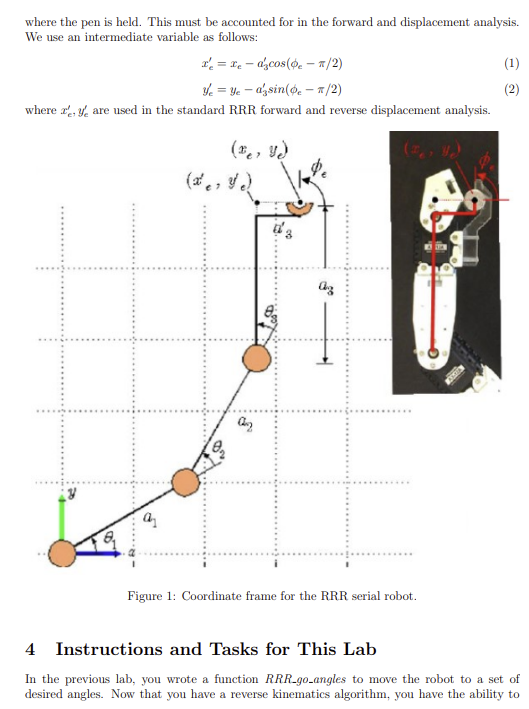
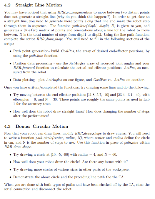
ME 4451 Lab 2 Handout RRR Serial Robot Servo Control 1 Objectives 1. Use inverse kinematics (RDA) to control the motion of an RRR serial robot. 2. Use the robot to draw a straight line and circle. 2 Prelab Assignment Read Lab 2 Handout. Create a Matlab script for Lab 2 tasks (Section 4) utilizing any commands needed from the Lab 1 handout, noting you will make use of your RRR_RDA function from HW 2. Please clearly comment your code. Your TA will check this off at the beginning of your lab section. Upon entering lab, do the following tasks and be prepared to answer the following questions - Identify the origin of your robot and the x and y axes - With a ruler, measure the link lengths of your robot. Compare these values to the values in your dh struct. Point to the location on your robot that represents the point (*e, ye) - Point to the distance represented by a 3 Coordinate System Fig. 1 shows the end-effector position (re, ye) and orientation (e), and link lengths (a). Furthermore, each joint angle (6) is defined positive in the counter-clockwise direction. An additional length (a) is for the lateral offset between link3 and the location on the gripper where the pen is held. This must be accounted for in the forward and displacement analysis. We use an intermediate variable as follows: x = x - azcos(-1/2) Yeye - azsin (0-1/2) where x, y are used in the standard RRR forward and reverse displacement analysis. (x, y) (x, y) 3 Figure 1: Coordinate frame for the RRR serial robot. (1) (2) 4 Instructions and Tasks for This Lab In the previous lab, you wrote a function RRR_go_angles to move the robot to a set of desired angles. Now that you have a reverse kinematics algorithm, you have the ability to set a desired end-effector position and orientation directly. You will write a function to move the robot to a given configuration, and then use it to move the robot along a straight line and in a circle. Connect to the computer and connect the serial communication just like you did in Lab 1. 4.1 RRR Inverse Kinematics Function As you saw in Lab 1, the RRR serial robot used in lab is controlled by setting the joint angles. However, in practice, it is preferable to be able to set the end-effector location directly. Therefore, you need a way to map the end-effector location to joint angles that you can send to the robot. This is exactly what is accomplished by the RRR_RDA function that you wrote for Homework 2. There are some slight additions that you will need to make in order to use your RRR_RDA function with the lab robot. You will implement these additions in a new function of the form RRR_reverse(dh, displ, elbowplus). The inputs are: dh - A structure containing the Denavit-Hartenberg (DH) parameters (link lengths, joint angles, etc.) for the lab robot. This structure can be loaded into your workspace by running data RRR.m. displ- A vector containing the end-effector position and orientation in the form [*e, ye, e], where x and y are in cm and phi, is in degrees. elbowplus - A boolean indicating whether to use the elbow plus (true) or elbow minus (false) RDA solution. The outputs are: dh - The input structure with the additional fields generated by your RRR_RDA func- tion. The steps for writing RRR.reverse are as follows: Convert to radians, as the equations you will use and the function you wrote for Homework 2 use angles in radians. In order to account for the offset of the pen from the center of the third link, shown in Fig. 1, you need to use a virtual end-effector location. Calculate the virtual end-effector location coordinates x and y using Equations 1 and 2, where a = 2.7 cm. Create a vector containing the desired virtual end-effector location and the value of o in radians: [Yes]. Load this vector into the field of dh that your RRR_RDA function uses as the end-effector location. Create a new field in dh named elbowplus and set it to the value of elbowplus. Call your RRR_RDA function and output the updated structure containing the joint angles to dh. You will now update your RRR_RDA function to include the elbow minus solution if it does not already. The steps for the elbow minus solution are the same as those for the elbow plus solution until the final step where and 2 are calculated. Review Lecture 4 if necessary. Add the elbow minus solution with the following step: Add a conditional that uses the elbow plus equations for and 02 if elbowplus is true. Otherwise, use the elbow minus equations for and 02. Later, you will use FDA and the measured joint angles to calculate and plot the actual end- effector locations. However, you will also need to account for the offset between the pen and the center of the third link as you did above for RDA. Write a function RRR-forward (dh) to accomplish this: Use your RRR_FDA function to retrieve the end-effector location from the joint angles. The result will be the virtual end-effector location. Rearrange Equations 1 and 2 and use them to calculate the actual end-effector location from and y with a = 2.7 cm. Output the structure with the updated end-effector location field. Now write a function RRR-go.configuration(dh, displ, elbowplus) that causes the end-effector to go to a given end-effector position and orientation. The inputs are the same as above. This function has no output. Instead, it moves the robot. Your function should: Calculate the necessary joint angles using RRR_reverse. Extract these angles from the output of RRR_reverse and convert them to degrees. Set the robot's joint angles. You may find your RRR-go_angles function from Lab 1 to be useful. Test RRR-go.configuration: Test your function using displ = [18, -6, -60] and elbowplus = 0. Next try using displ = [18, -6, -60] and elbowplus = 1. Also try displ = [-15, -15, -150] in both the elbowplus and elbowminus configurations Show the results to the TA, and try some other points/orientations in the workspace. 4.2 Straight Line Motion You may have noticed that using RRR_go_configuration to move between two distant points does not generate a straight line (why do you think this happens?). In order to get close to a straight line, you need to generate more points along that line and make the robot step through them in sequence. The function path_line(displ1, displ2, N) is given to you, and generates a (N+1)x3 matrix of points and orientations along a line for the robot to move between. N is the total number of steps from displl to displ2. Using the line path function, complete the script RRR_draw_shape. You will need to fill in the following sections of the script: Path point generation- build GoalPos, the array of desired end-effector positions, by using the path_line function. Position data processing - use the ActAngles array of recorded joint angles and your RRR_forward function to calculate the actual end-effector positions, ActPos, as mea- sured from the robot. Data plotting - plot ActAngles on one figure, and GoalPos vs. ActPos on another. Once you have written/completed the functions, try drawing some lines and do the following: Try moving between the end-effector positions [11.8, 5.7, -40] and [23.4, -3.1, -40], with elbowplus = 0, and N = 30. These points are roughly the same points as used in Lab 1 for the accuracy tests. 4.3 How well does the robot draw straight lines? How does changing the number of steps alter the performance? Bonus: Circular Motion Now that your robot can draw lines, modify RRR_draw_shape to draw circles. You will need to write a function path_circle(center, radius, N), where center and radius define the circle in cm, and N is the number of steps to use. Use this function in place of path_line within RRR_draw_shape. Try drawing a circle at [10, -5, -90] with radius = 4, and N = 60. How well does your robot draw the circle? Are there any issues with it? Try drawing more circles of various sizes in other parts of the workspace. Demonstrate the above circle and the preceding line path tho the TA. When you are done with both types of paths and have been checked off by the TA, close the serial connection and disconnect the robot.
Step by Step Solution
There are 3 Steps involved in it
Step: 1

Get Instant Access to Expert-Tailored Solutions
See step-by-step solutions with expert insights and AI powered tools for academic success
Step: 2

Step: 3

Ace Your Homework with AI
Get the answers you need in no time with our AI-driven, step-by-step assistance
Get Started


