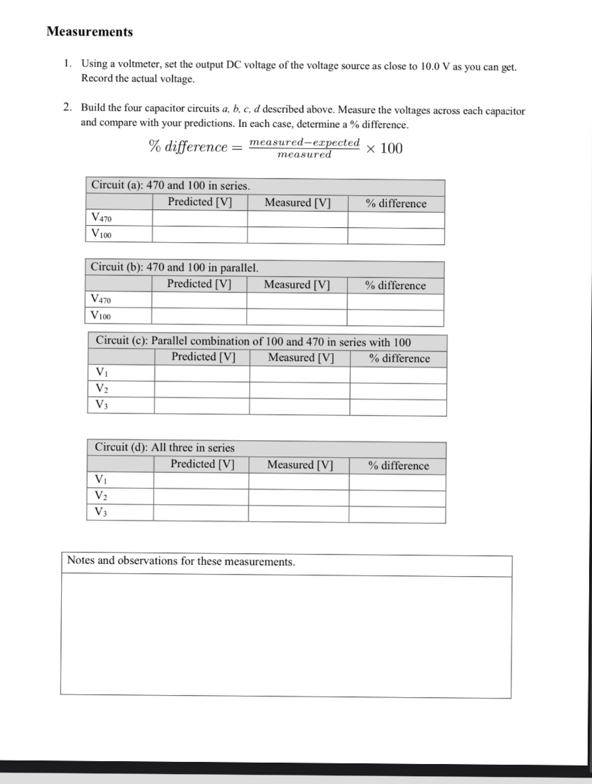
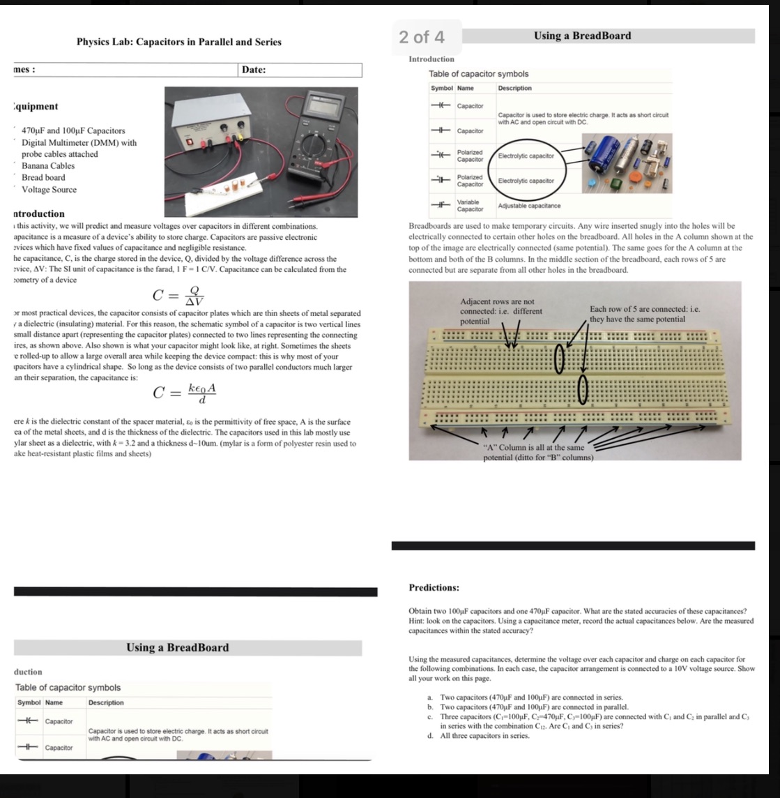
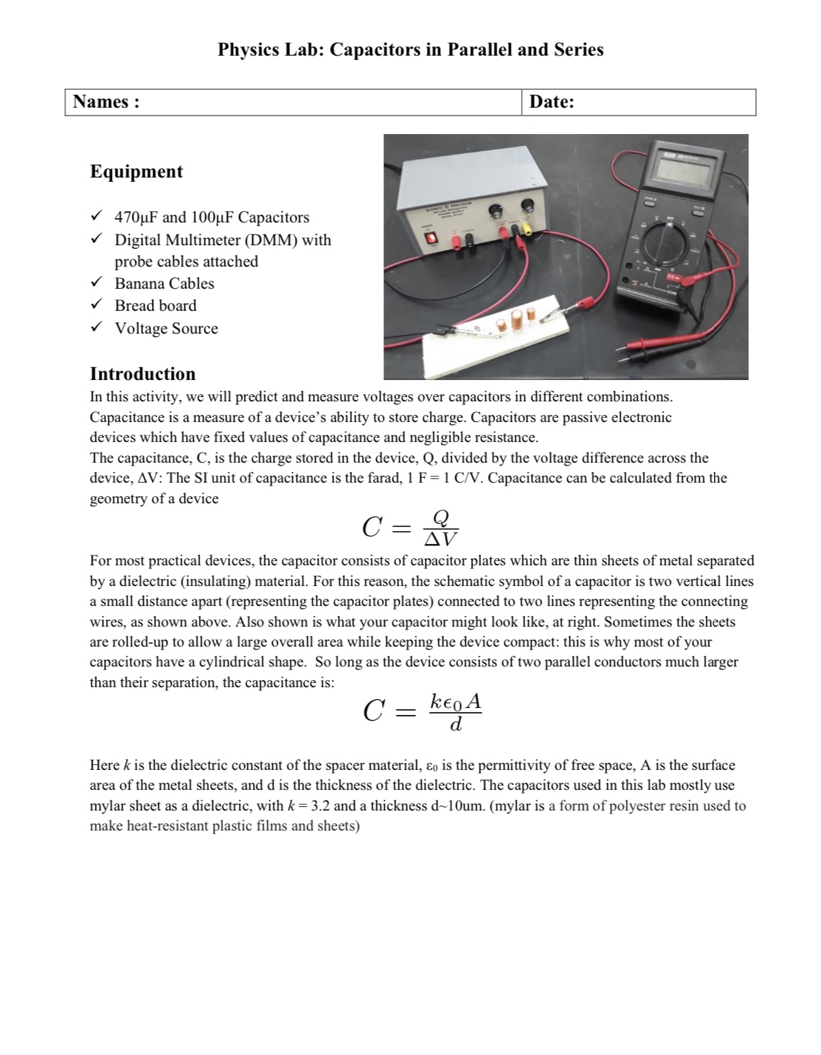
Measurements 1. Using a voltmeter, set the output DC voltage of the voltage source as close to 10.0 V as you can get. Record the actual voltage. 2. Build the four capacitor circuits a, b, c, d described above. Measure the voltages across each capacitor and compare with your predictions. In each case, determine a % difference. difference = measured-expected x 100 measured Circuit (a): 470 and 100 in series. Predicted [V] Measured [V] % difference V470 V 100 Circuit (b): 470 and 100 in parallel. Predicted [V] Measured [V] % difference V470 V100 Circuit (c): Parallel combination of 100 and 470 in series with 100 Predicted [V] Measured [V] % difference V1 V2 Circuit (d): All three in series Predicted [V] Measured [V] % difference VI V2 V 3 Notes and observations for these measurements.Physics Lab: Capacitors in Parallel and Series 2 of 4 Using a BreadBoard Introduction mes : Date: Table of capacitor symbols Symbol Name Description quipment -If Capacitor Capacitor is used to store electric charge. It acts as short circuit with AC and open circuit with DC. 470uF and 100uF Capacitors Capacitor Digital Multimeter (DMM) with probe cables attached Polarized Capacitor lectrolytic capacitor Banana Cables Bread board Polarized Capacito Electrolytic cap Voltage Source Variable Adjustable capacitance ntroduction . this activity, we will predict and measure voltages over capacitors in different combinations. Breadboards are used to make temporary circuits. Any wire inserted snugly into the holes will be apacitance is a measure of a device's ability to store charge. Capacitors are passive electronic electrically connected to certain other holes on the breadboard. All holes in the A column shown at the :vices which have fixed values of capacitance and negligible resistance. top of the image are electrically connected (same potential). The same goes for the A column at the he capacitance, C, is the charge stored in the device, Q, divided by the voltage difference across the bottom and both of the B columns. In the middle section of the breadboard, each rows of 5 are rvice, AV: The SI unit of capacitance is the farad, I F = 1 C/V. Capacitance can be calculated from the connected but are separate from all other holes in the breadboard. cometry of a device C = AV Adjacent rows are not or most practical devices, the capacitor consists of capacitor plates which are thin sheets of metal separated connected: i.e. different Each row of 5 are connected: i.c. a dielectric (insulating) material. For this reason, the schematic symbol of a capacitor is two vertical lines potential hey have the same potential small distance apart (representing the capacitor plates) connected to two lines representing the connecting ires, as shown above. Also shown is what your capacitor might look like, at right. Sometimes the sheets e rolled-up to allow a large over area while keeping the device compact: this is why most of your pacitors have a cylindrical shape. So long as the device consists of two parallel conductors much larger an their separation, the capacitance is: C = Ken A d ere & is the dielectric constant of the spacer material, So is the permittivity of free space, A is the surface ca of the metal sheets, and d is the thickness of the dielectric. The capacitors used in this lab mostly use ylar sheet as a dielectric, with A = 3.2 and a thickness d-10um. (mylar is a form of polyester resin used to "A" Column is all at the same ake heat-resistant plastic films and sheets) potential (ditto for "B" columns Predictions: Obtain two 100 F capacitors and one 470pF capacitor. What are the stated accuracies of these capacitances? Hint: look on the capacitors. Using a capacitance meter, record the actual capacitances below. Are the measured capacitances within the stated accuracy? Using a BreadBoard Using the measured capacitances, determine the voltage over each capacitor and charge on each capacitor for duction the following combinations. In each case, the capacitor arrangement is connected to a 10V voltage source. Show all your work on this page. Table of capacitor symbols Symbol Name Description a. Two capacitors (470 F and 100uF) are connected in series. Two capacitors (470 F and 100uF) are connected in parallel. - Capacitor c. Three capacitors (Ci=100pF, C=470 F. Cy=100pF) are connected with Ci and Ca in parallel and Cy Capacitor is used to store electric charge. It acts as short circus in series with the combination Cuz. Are Ci and C, in series? with AC and open circuit with DC. d. All three capacitors in series. CapacitorPhysics Lab: Capacitors in Parallel and Series Equipment / 4'?0uF and lOOpF Capacitors 1/ Digital Multimeter (DMM) with probe cables attached Banana Cables Bread board 1/ Voltage Source xx Introduction In this activity, we will predict and measure voltages over capacitors in different combinations. Capacitance is a measure of a device's ability to store charge. Capacitors are passive electronic devices which have fixed values of capacitance and negligible resistance. The capacitance, C, is the charge stored in the device, Q, divided by the voltage difference across the device, AV: The SI unit of capacitance is the farad, 1 F = 1 CN. Capacitance can be calculated from the geometry of a device 0 = Q AV For most practical devices, the capacitor consists of capacitor plates which are thin sheets of metal separated by a dielectric (insulating) material. For this reason, the schematic symbol of a capacitor is two vertical lines a small distance apart (representing the capacitor plates) connected to two lines representing the connecting wires, as shown above. Also shown is what your capacitor might look like, at right. Sometimes the sheets are rolled-up to allow a large overall area while keeping the device compact: this is why most of your capacitors have a cylindrical shape. So long as the device consists of two parallel conductors much larger than their separation, the capacitance is: C : keo A d Here It is the dielectric constant of the spacer material, an is the permittivity of free space, A is the surface area of the metal sheets, and d is the thickness of the dielectric. The capacitors used in this lab mostly use mylar sheet as a dielectric, with k = 3.2 and a thickness d~101nn. (mylar is a form of polyester resin used to make heat-resistant plastic lms and sheets)


