Modify the HDL code for the single-cycle ARM processor, given in Section 7.6.1, to handle the instructions from the list (EOR, LSR, TEQ, RSB). Enhance the testbench, given in Section 7.6.3, to test the new instruction.
(a) EOR (b) LSR (c) TEQ (d) RSB
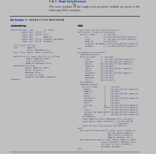
7.6.1 Single-Cycle Processor The main modules of the single-cycle processor module are given in the following HDL examples. HDL Example 7.1 SINGLE-CYCLE PROCESSOR System Verilog module arm (input logic VHDL 1i brary 1EEE; use I EEE.STOLo41 1164.11 entity rm s .. singlecycle process or clk, reset, autput logic [31:0] P, input logic [31:0] Instr, output logic output logic [31:0] ALUResult, writeDets, nput logic [31:0] Readleta); porticlk, reset: n STO LOGIC out STO-LOGIC-VECTOR(31 down t 0); in STD-LOGIC-VECTOR(31 downto); out STO_LONIC Mert rite PC: Memir ite: ri teleta: logic [3:0] ALUFlags aut STOLLOSIC_VECTaRI 31 dawnta 0) STO-LOGIC-VECTOR (31 in downta)); Regwrite lagic [1:01 RegSrc, lmmSre, ALUCon tral; architecturestruct of armis component contraller port(clk, resat inSTO-LOGIC; controller ciclk, reset, Instr[31:12], AL UF1 ags, RegSrc, Regirite, ImmSre, in STD-LOGIC-VECTOR!down to 12); in STO-LOGIC-VECTORdawn to a); out STQ-Loaic-VECTOR( 1 downto)) ; out STO-LOGIC; out STO LOG IC_VECTOR(1 downto 0): out STILLOGC; out STO LOGICVECTaRe 1 downto 0); out STD-LOGIC; out STOLOG IC; out S TOLOG IC): ALUSrc, ALUControl. Memdrite, Mentakeg, PCSrc); A LUF 1ags.: Regsrc: Regdrite detapath dp(clk, res et Reg Sre, Regwrite, Immrc, ALU Src, ALUControl, MentaReg, PCSre, ALUFlags, PC, Instr. ALU Result, WriteDate, ReadDeta); mSrc: ALUSrc: ALUC ont ral: Memdrite: Ment ake q: endmodule compon ent da tapath reset: port (cl k, n n STOLONIC VECTOR(1 downto 0): in STD-LOGIC; n STO LOsic VECTaR (1 downto 0) in STOLOGIC n STO LOSIC VECTOR(1 downto 0); in STQ-LOGIC; n STO LOS IC; out ST LLOG I VECTOR ( 3 downto a); huffer STO LOGIC VECTOR(31 downto 0); n STO LOSIC VECTOR 31 downto 0); STD-LOGIC; RegSrc: Regrite ImmSrc: ALUSrc AL UContral: Menta Reg: PCSrc: AL UF1 ags PC: Instr ALUResult, writeleta:buffer STO L0S1CVECTOR(31 downto 0): ReadData n STO LOGIC VECTORK 31 downto 0)) end compon ent; signal Regwrite, ALUSrc, Mertokeg, PCSre: STLOGIC; signal Reg Src, lSre, ALUContral. STQ-LOGIC-VECTOR (1 downt od); signa1 ALUFlags: STOLOSIC VECTOR3 down to 0); cont: contraller part mapiclk, reset, Instri 31 downto 12), ImSre, ALuS re, ALUCantral, Memirite, MemtoReg, PCSrc) dp: detapath port map(clk, reset, RegSre, Regrite, Imm Sre, ALUSrc, AL UKontral, Memto Reg, PCSrc, ALUFlags, PC, Instr, ALUResult, 7.6.1 Single-Cycle Processor The main modules of the single-cycle processor module are given in the following HDL examples. HDL Example 7.1 SINGLE-CYCLE PROCESSOR System Verilog module arm (input logic VHDL 1i brary 1EEE; use I EEE.STOLo41 1164.11 entity rm s .. singlecycle process or clk, reset, autput logic [31:0] P, input logic [31:0] Instr, output logic output logic [31:0] ALUResult, writeDets, nput logic [31:0] Readleta); porticlk, reset: n STO LOGIC out STO-LOGIC-VECTOR(31 down t 0); in STD-LOGIC-VECTOR(31 downto); out STO_LONIC Mert rite PC: Memir ite: ri teleta: logic [3:0] ALUFlags aut STOLLOSIC_VECTaRI 31 dawnta 0) STO-LOGIC-VECTOR (31 in downta)); Regwrite lagic [1:01 RegSrc, lmmSre, ALUCon tral; architecturestruct of armis component contraller port(clk, resat inSTO-LOGIC; controller ciclk, reset, Instr[31:12], AL UF1 ags, RegSrc, Regirite, ImmSre, in STD-LOGIC-VECTOR!down to 12); in STO-LOGIC-VECTORdawn to a); out STQ-Loaic-VECTOR( 1 downto)) ; out STO-LOGIC; out STO LOG IC_VECTOR(1 downto 0): out STILLOGC; out STO LOGICVECTaRe 1 downto 0); out STD-LOGIC; out STOLOG IC; out S TOLOG IC): ALUSrc, ALUControl. Memdrite, Mentakeg, PCSrc); A LUF 1ags.: Regsrc: Regdrite detapath dp(clk, res et Reg Sre, Regwrite, Immrc, ALU Src, ALUControl, MentaReg, PCSre, ALUFlags, PC, Instr. ALU Result, WriteDate, ReadDeta); mSrc: ALUSrc: ALUC ont ral: Memdrite: Ment ake q: endmodule compon ent da tapath reset: port (cl k, n n STOLONIC VECTOR(1 downto 0): in STD-LOGIC; n STO LOsic VECTaR (1 downto 0) in STOLOGIC n STO LOSIC VECTOR(1 downto 0); in STQ-LOGIC; n STO LOS IC; out ST LLOG I VECTOR ( 3 downto a); huffer STO LOGIC VECTOR(31 downto 0); n STO LOSIC VECTOR 31 downto 0); STD-LOGIC; RegSrc: Regrite ImmSrc: ALUSrc AL UContral: Menta Reg: PCSrc: AL UF1 ags PC: Instr ALUResult, writeleta:buffer STO L0S1CVECTOR(31 downto 0): ReadData n STO LOGIC VECTORK 31 downto 0)) end compon ent; signal Regwrite, ALUSrc, Mertokeg, PCSre: STLOGIC; signal Reg Src, lSre, ALUContral. STQ-LOGIC-VECTOR (1 downt od); signa1 ALUFlags: STOLOSIC VECTOR3 down to 0); cont: contraller part mapiclk, reset, Instri 31 downto 12), ImSre, ALuS re, ALUCantral, Memirite, MemtoReg, PCSrc) dp: detapath port map(clk, reset, RegSre, Regrite, Imm Sre, ALUSrc, AL UKontral, Memto Reg, PCSrc, ALUFlags, PC, Instr, ALUResult