Answered step by step
Verified Expert Solution
Link Copied!

Question

1 Approved Answer

must be done in c++ thank you RS 1. The electric circuit shown in the figure below is designed by specifying values for the six

must be done in c++ thank you image text in transcribed
image text in transcribed
RS 1. The electric circuit shown in the figure below is designed by specifying values for the six resistances R1 through R6. R R R w w 02 . w R 15 V R 2 + -2V We The figure indicates that the output voltage of the circuit must be 15 Volts when the input voltage is -2 Volts. Consequently, the circuit will operate correctly only when the six resistances satisfy the following equation: (R1 + R2)R.RS = 7.5 (R3 +R2)R, RS Sample values are given in the file (resistances.txt) contains several proposed designs for the circuit. Each line of the file provides the six resistances listed in order. Some of the designs may not be correct. Write a program that reads the values from the user and print out on the screen whether this is a bad design or a good design. Sample output: Bad Design values: 10 Good Design values: 10 15 75 10 10 20 75 10 10 10 10 Resistance.txt 10 10 25 5 2 6 1 40 2 25 35 15 10 75 10 34 15 37.5 5 5 12 5 15 7.5 1 100 10 15 2 25 25 20 10 20 10 75 10 65 75 37.5 5 24 84 24 12 7.5 1 5 25 15 2 25 25 15 5 10 10 5 5 34 42 1 30 2 25 20

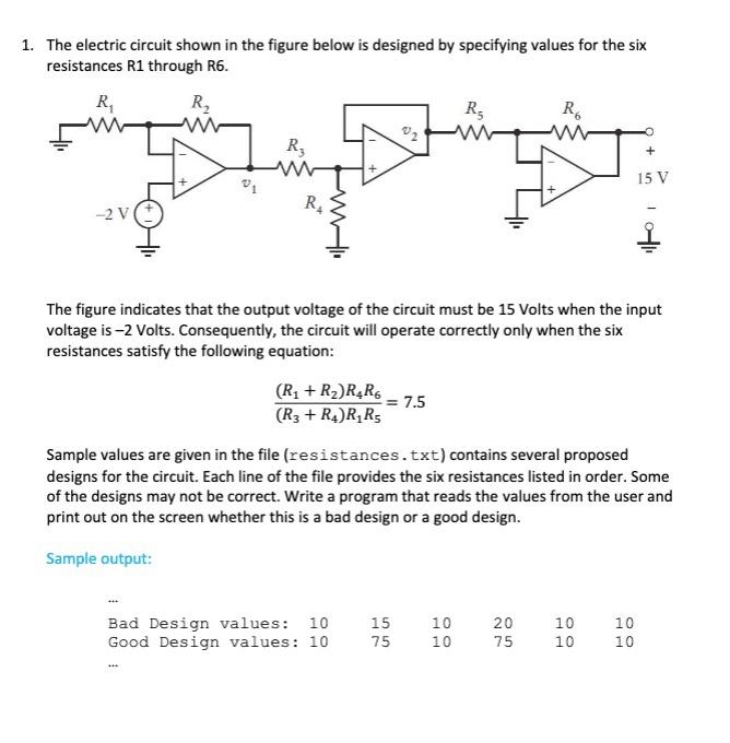
Step by Step Solution

There are 3 Steps involved in it

Step: 1

blur-text-image

Get Instant Access to Expert-Tailored Solutions

See step-by-step solutions with expert insights and AI powered tools for academic success

Step: 2

blur-text-image

Step: 3

blur-text-image

Ace Your Homework with AI

Get the answers you need in no time with our AI-driven, step-by-step assistance

Get Started

Recommended Textbook for

Information Modeling And Relational Databases

Authors: Terry Halpin, Tony Morgan

2nd Edition

0123735688, 978-0123735683

More Books

Students also viewed these Databases questions