

Question: Need a help on writing a conclusion for heat exchanger experiment Experiment HE: Heat Exchangers Objective To investigate the effect on the overall heat transfer
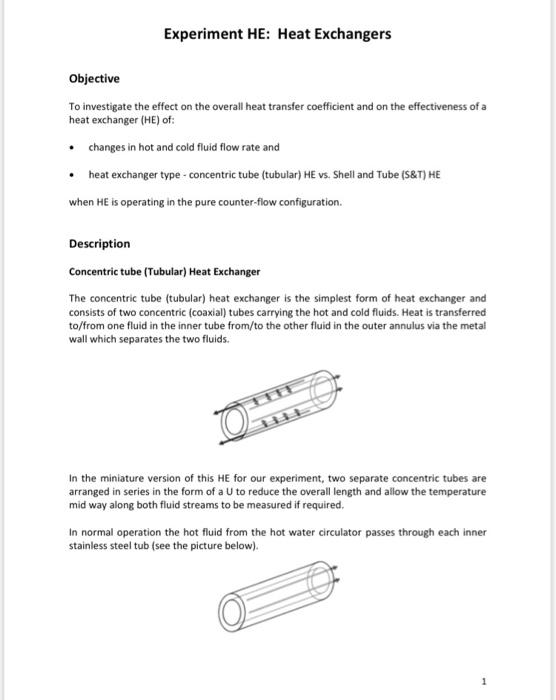
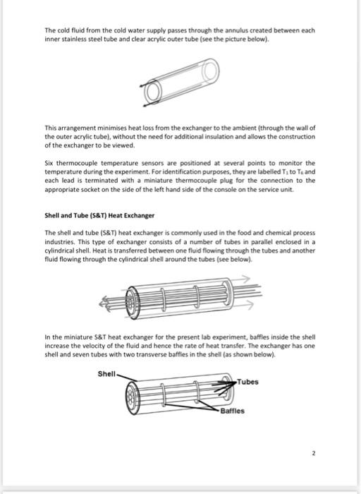
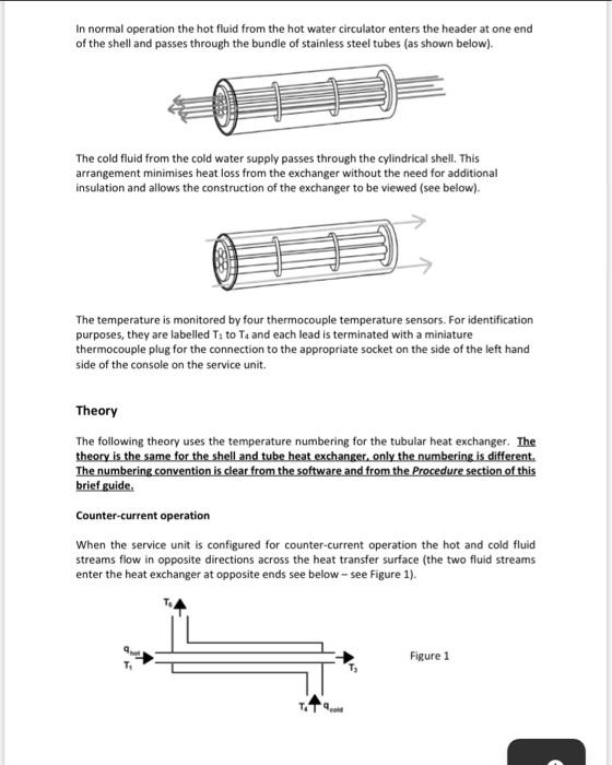
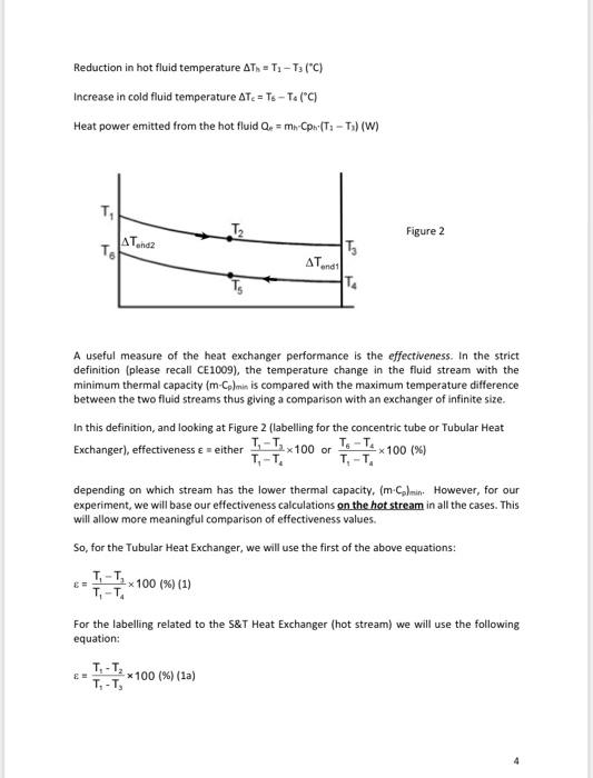
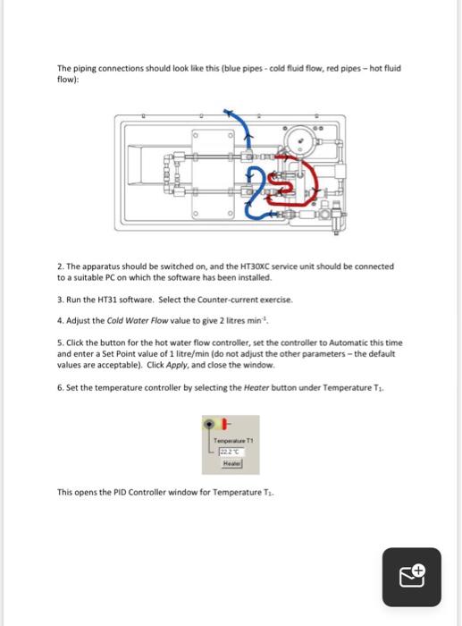
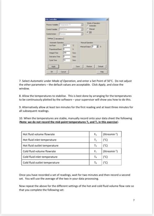
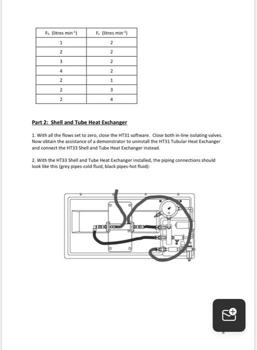
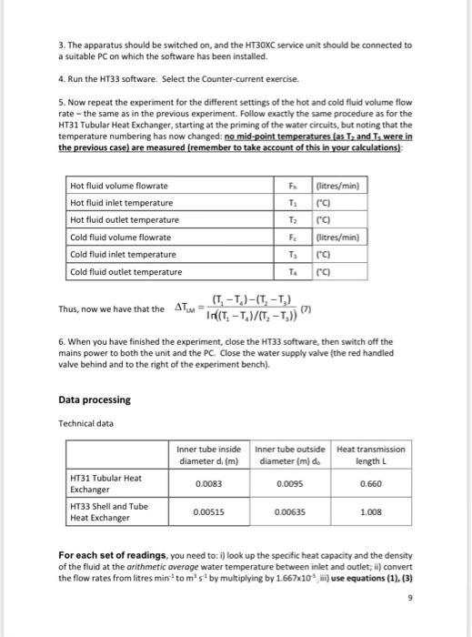
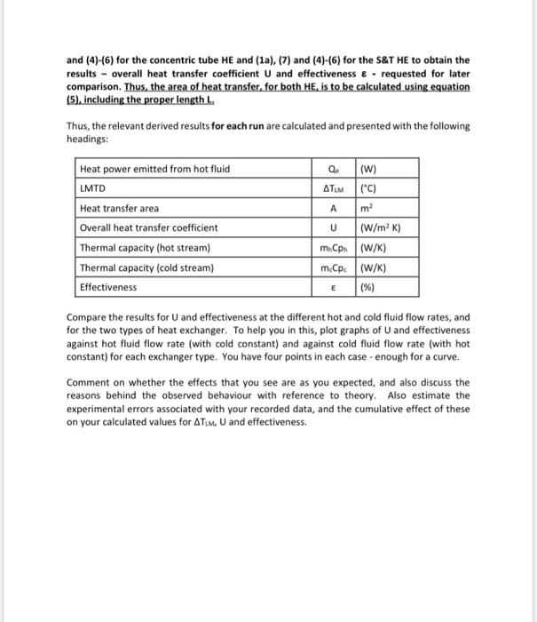
Experiment HE: Heat Exchangers Objective To investigate the effect on the overall heat transfer coefficient and on the effectiveness of a heat exchanger (HE) of: changes in hot and cold fluid flow rate and heat exchanger type - concentric tube (tubular) HE vs. Shell and Tube (S&T) HE when He is operating in the pure counter-flow configuration. Description Concentric tube (Tubular) Heat Exchanger The concentric tube (tubular) heat exchanger is the simplest form of heat exchanger and consists of two concentric (coaxial) tubes carrying the hot and cold fluids. Heat is transferred to/from one fluid in the inner tube from/to the other fluid in the outer annulus via the metal wall which separates the two fluids. Oh In the miniature version of this HE for our experiment, two separate concentric tubes are arranged in series in the form of a U to reduce the overall length and allow the temperature mid way along both fluid streams to be measured if required. In normal operation the hot fluid from the hot water circulator passes through each inner stainless steel tub (see the picture below) The cold fluid from the cold water supply passes through the annulus created between each inner stainless steel tube and clear acrylic outer tube (see the picture below). This arrangement minimises heat loss from the exchanger to the ambient (through the wall of the outer acrylic tube), without the need for additional insulation and allows the construction of the exchanger to be viewed Six thermocouple temperature sensors are positioned at several points to mon temperature during the experiment. For identification purposes, they are labelled T: to Te and each lead is terminated with a miniature thermocouple plug for the connection to the appropriate socket on the side of the left hand side of the console on the service unit. the Shell and Tube (S&T) Heat Exchanger The shell and tube (5&T) heat exchanger is commonly used in the food and chemical process industries. This type of exchanger consists of a number of tubes in parallel enclosed in a cylindrical shell. Heat is transferred between one fluid flowing through the tubes and another fluid flowing through the cylindrical shell around the tubes (see below). In the miniature S&T heat exchanger for the present lab experiment, baffles inside the shell increase the velocity of the fluid and hence the rate of heat transfer. The exchanger has one shell and seven tubes with two transverse baffles in the shell (as shown below). Shell Tubes Baffles 2 In normal operation the hot fluid from the hot water circulator enters the header at one end of the shell and passes through the bundle of stainless steel tubes (as shown below). The cold fluid from the cold water supply passes through the cylindrical shell. This arrangement minimises heat loss from the exchanger without the need for additional insulation and allows the construction of the exchanger to be viewed (see below). The temperature is monitored by four thermocouple temperature sensors. For identification purposes, they are labelled T. to Te and each lead is terminated with a miniature thermocouple plug for the connection to the appropriate socket on the side of the left hand side of the console on the service unit Theory The following theory uses the temperature numbering for the tubular heat exchanger. The theory is the same for the shell and tube heat exchanger, only the numbering is different. The numbering convention is clear from the software and from the Procedure section of this brief guide. Counter-current operation When the service unit is configured for counter-current operation the hot and cold fluid streams flow in opposite directions across the heat transfer surface (the two fluid streams enter the heat exchanger at opposite ends see below - see Figure 1). Figure 1 Reduction in hot fluid temperature ATA = T.-T (C) Increase in cold fluid temperature AT = T6 - Ta (C) Heat power emitted from the hot fluid Q = m Cpr (T: -T) (W) T T2 Figure 2 AT.cz TE TS AT anail TA A useful measure of the heat exchanger performance is the effectiveness. In the strict definition (please recall CE1009), the temperature change in the fluid stream with the minimum thermal capacity (m-cplmin is compared with the maximum temperature difference between the two fluid streams thus giving a comparison with an exchanger of infinite size. In this definition, and looking at Figure 2 (labeling for the concentric tube or Tubular Heat Exchanger), effectiveness e = either 1 x 100 or 1-T x 100(%) T. -T T.-T. depending on which stream has the lower thermal capacity. (m.Colmin. However, for our experiment, we will base our effectiveness calculations on the hot stream in all the cases. This will allow more meaningful comparison of effectiveness values. So, for the Tubular Heat Exchanger, we will use the first of the above equations: T.-T7x100 (%) (1) EE T, T. For the labelling related to the S&T Heat Exchanger (hot stream) we will use the following equation: T.-T, T-T, *100 (%) (1a) E- Heat exchange Because the temperature difference between the hot and cold fluid streams varies along the length of the heat exchanger it is necessary to derive an average temperature difference (driving force) from which heat transfer calculations can be performed. This average temperature difference is called the Logarithmic Mean Temperature Difference (LMTD) ATM (please recall CE 1009): ATM AT . In(AT./AT...) (2) Therefore, for the labelling given above the case of the Tubular Heat Exchanger: ? (T3-T)-(T-T) (3) In((T-T/T, -T.)) The heat transmission area in the exchanger can be calculated with minimal error using the arithmetic mean diameter of the inner tube (as the tube is relatively thin-walled). Arithmetic mean diameter (m) .. 2 Heat transmission length L (m) Heat transmission area Ardel (m) (5) Overall Heat Transfer Coefficient U Q. (Wm-*")(6) where Q. is the emitted heat power as indicated above. Experimental Procedure Part 1: HT31 Tubular Heat Exchanger 1. Ensure that the equipment has been set up and the HT31 Tubular Heat Exchanger installed as described in this manual, with a cold water supply connected and the pressure regulator adjusted (see below). This will normally have been done for you. The piping connections should look like this (blue pipes - cold fluid flow, red pipes - hot fluid flow): Lo = CODE 22 2. The apparatus should be switched on, and the HT30XC service unit should be connected to a suitable PC on which the software has been installed. 3. Run the HT31 software. Select the Counter-current exercise. 4. Adjust the Cold Water Flow value to give 2 litres min. 5. Click the button for the hot water flow controller, set the controller to Automatic this time and enter a Set Point value of 1 litre/min (do not adjust the other parameters - the default values are acceptable). Click Apply, and close the window 6. Set the temperature controller by selecting the Heater button under Temperature Tu. 1 This opens the PID Controller window for Temperature Tu. 7. Select Automatic under Mode of Operation, and enter a Set Point of 50C. Do not adjust the other parameters - the default values are acceptable. Click Apply, and close the window. 8. Allow the temperatures to stabilise. This is best done by arranging for the temperatures to be continuously plotted by the software - your supervisor will show you how to do this. 9. Alternatively allow at least ten minutes for the first reading and at least three minutes for all subsequent readings 10. When the temperatures are stable, manually record onto your data sheet the following (Note: we do not record the mid-point temperatures T, and Ts in this exercise) Hot fluid volume flowrate Hot fluid inlet temperature Hot fluid outlet temperature Cold fluid volume flowrate Cold fluid inlet temperature Cold fluid outlet temperature Flitresmin") T: ("C) T) (C) F (litresmin) TA (C) TO (C) Once you have recorded a set of readings, wait for two minutes and then record a second set. You will use the average of the two in your data processing Now repeat the above for the different settings of the hot and cold fluid volume flow rate so that you complete the following set: 7 Fu (litres min) Fs (litres min) 2 1 2 2 3 2. 4 2. 2 1 2 3 2 4 Part 2: Shell and Tube Heat Exchanger 1. With all the flows set to zero, close the HT31 software. Cose both in-line isolating valves. Now obtain the assistance of a demonstrator to uninstall the HT31 Tubular Heat Exchanger and connect the HT33 Shell and Tube Heat Exchanger instead. 2. With the HT33 Shell and Tube Heat Exchanger installed, the piping connections should look like this (grey pipes-cold fluid, black pipes-hot fluid): TU 3. The apparatus should be switched on, and the HT30XC service unit should be connected to a suitable PC on which the software has been installed. 4. Run the HT33 software. Select the Counter-current exercise. 5. Now repeat the experiment for the different settings of the hot and cold fluid volume flow rate the same as in the previous experiment. Follow exactly the same procedure as for the HT31 Tubular Heat Exchanger, starting at the priming of the water circuits, but noting that the temperature numbering has now changed: no mid-point temperatures (as Tz and Is were in the previous case) are measured (remember to take account of this in your calculations) FA T: T: Hot fluid volume flowrate Hot fluid inlet temperature Hot fluid outlet temperature Cold fluid volume flowrate Cold fluid inlet temperature Cold fluid outlet temperature (litres/min) rc) (C) (litres/min) ["C) F IS T4 [C) (T. -T.)-(T. -T) Thus, now we have that the ATM (7) INT, -T/T, -T)) 6. When you have finished the experiment, close the HT33 software, then switch off the mains power to both the unit and the PC. Close the water supply valve (the red handled valve behind and to the right of the experiment bench). Data processing Technical data Inner tube inside diameter di (m) 0.0083 Inner tube outside Heat transmission diameter (m) de length L 0.0095 0.660 HT31 Tubular Heat Exchanger HT33 Shell and Tube Heat Exchanger 0.00515 0.00635 1.008 For each set of readings, you need to: i) look up the specific heat capacity and the density of the fluid at the arithmetic average water temperature between inlet and outlet; ii) convert the flow rates from litres min-toms by multiplying by 1.667x10.9 m use equations (1), (3) and (4)-(6) for the concentric tube HE and (1a), (7) and (4)-(6) for the S&T HE to obtain the results - overall heat transfer coefficient U and effectiveness & requested for later comparison. Thus, the area of heat transfer, for both He, is to be calculated using equation (5), including the proper length L. Thus, the relevant derived results for each run are calculated and presented with the following headings: Q (W) ATUM (C) ma Heat power emitted from hot fluid LMTD Heat transfer area Overall heat transfer coefficient Thermal capacity (hot stream) Thermal capacity (cold stream) Effectiveness U (W/mK) m.ph (W/K) mcCpe (W/K) (%) E Compare the results for U and effectiveness at the different hot and cold fluid flow rates, and for the two types of heat exchanger. To help you in this, plot graphs of U and effectiveness against hot fluid flow rate (with cold constant) and against cold fluid flow rate (with hot constant) for each exchanger type. You have four points in each case - enough for a curve. Comment on whether the effects that you see are as you expected, and also discuss the reasons behind the observed behaviour with reference to theory. Also estimate the experimental errors associated with your recorded data, and the cumulative effect of these on your calculated values for ATM, U and effectiveness
Step by Step Solution
There are 3 Steps involved in it

Get step-by-step solutions from verified subject matter experts