Answered step by step
Verified Expert Solution
Question
1 Approved Answer
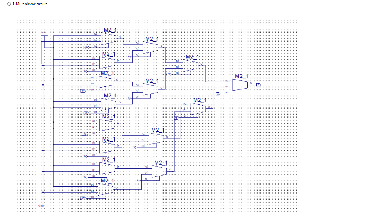
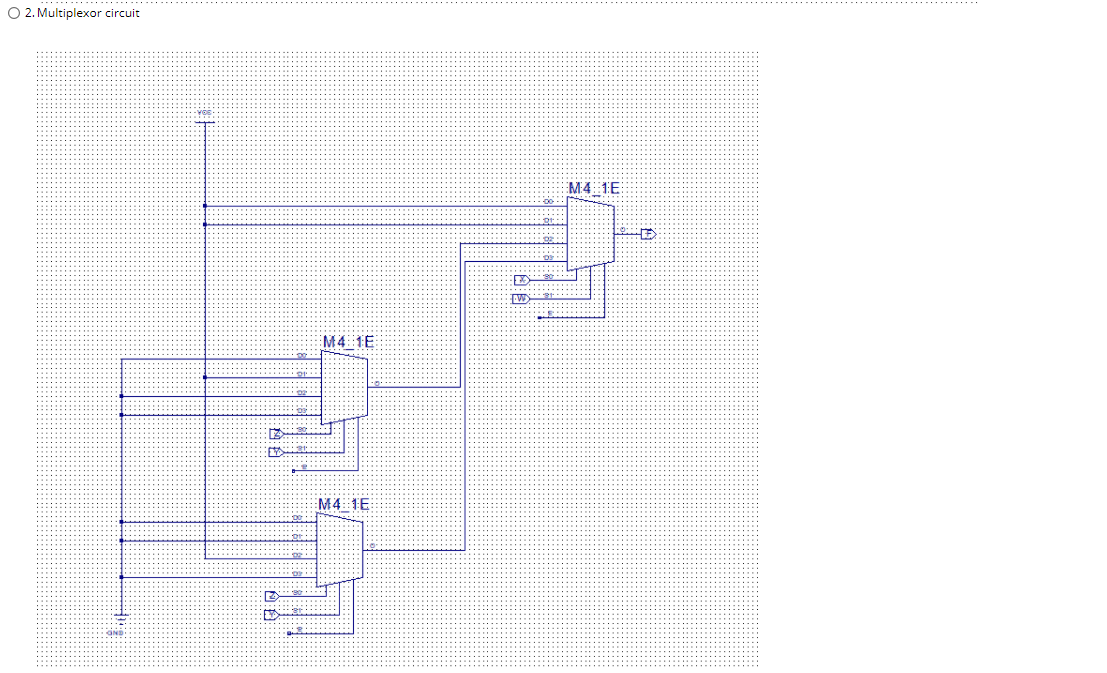
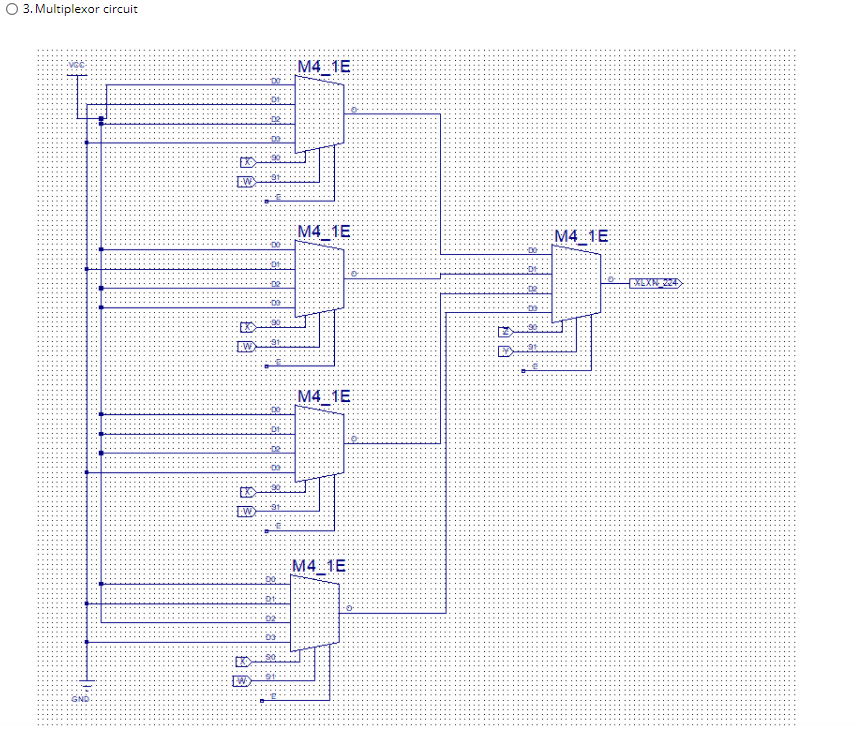
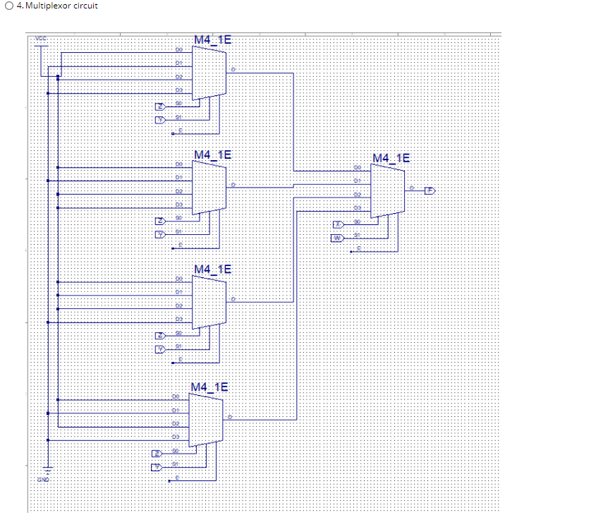
Need some help with a compsci problem - Question 8 Given window sensors (w, x, y and z), that output a 0 when the window
Need some help with a compsci problem -
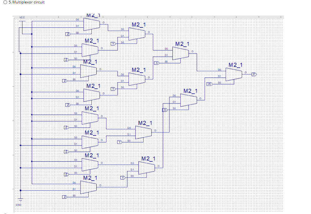
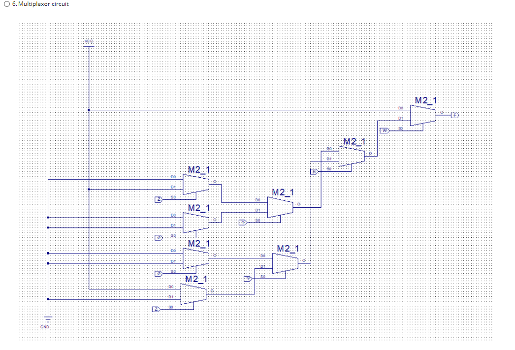
Question 8 Given window sensors (w, x, y and z), that output a 0 when the window is open and a 1 otherwise, what is the correct implementation of a circuit that will output a 1 in the following conditions using only 4 to 1 multiplexors: window z is open and no other windows are open or both windows x and y are open but z is closed anytime w is open regardless of other windows Remember: VCC represents a constant 1 and GND represents a constant o. Do not worry about the Enable input for the multiplexor (this question is not baout Xilinx) O 1. Multiplexor circuit M2_1 VGE M21 M2_1 30 M2:1 .80 M21 Y M2_1 M21 W E M2:1 M2:1 M2_1 M2_1 M2_1 M2:1 M2:1 M2_1 EX AW GND 2. Multiplexor circuit M4: 1E M4:1E M4:15 E 3. Multiplexor circuit VGC M41E 01: AW M4 1E M41E AW M4 1E 00: RW M4.15 01: 4. Multiplexor circuit M4:15 M4 15 M4 15 01 AW M41E DO 2 M4 15 5. Multiplexor circuit M2_1 -30 07 M21 M2_1 M21 M21 M2_1 M2_1 100 B so M2:1 M21 22 M2_1 M21 M21 M2_1 M2:1 M21 6. Multiplexor circuit M21 -W M2_1 leto M2_1 M2_1 2 M2_1 ER M2_1 M21 test 30 M21 Question 8 Given window sensors (w, x, y and z), that output a 0 when the window is open and a 1 otherwise, what is the correct implementation of a circuit that will output a 1 in the following conditions using only 4 to 1 multiplexors: window z is open and no other windows are open or both windows x and y are open but z is closed anytime w is open regardless of other windows Remember: VCC represents a constant 1 and GND represents a constant o. Do not worry about the Enable input for the multiplexor (this question is not baout Xilinx) O 1. Multiplexor circuit M2_1 VGE M21 M2_1 30 M2:1 .80 M21 Y M2_1 M21 W E M2:1 M2:1 M2_1 M2_1 M2_1 M2:1 M2:1 M2_1 EX AW GND 2. Multiplexor circuit M4: 1E M4:1E M4:15 E 3. Multiplexor circuit VGC M41E 01: AW M4 1E M41E AW M4 1E 00: RW M4.15 01: 4. Multiplexor circuit M4:15 M4 15 M4 15 01 AW M41E DO 2 M4 15 5. Multiplexor circuit M2_1 -30 07 M21 M2_1 M21 M21 M2_1 M2_1 100 B so M2:1 M21 22 M2_1 M21 M21 M2_1 M2:1 M21 6. Multiplexor circuit M21 -W M2_1 leto M2_1 M2_1 2 M2_1 ER M2_1 M21 test 30 M21Step by Step Solution
There are 3 Steps involved in it
Step: 1
Get Instant Access to Expert-Tailored Solutions
See step-by-step solutions with expert insights and AI powered tools for academic success
Step: 2
Step: 3
Ace Your Homework with AI
Get the answers you need in no time with our AI-driven, step-by-step assistance
Get Started