

Question
Note: Hello, I know you can't answer all the questions (its one question per post). I wish I could post them one by one but
Note: Hello, I know you can't answer all the questions (its one question per post). I wish I could post them one by one but I know the same person won't answer them all. If you can answer most of them I would appreciate it very much.
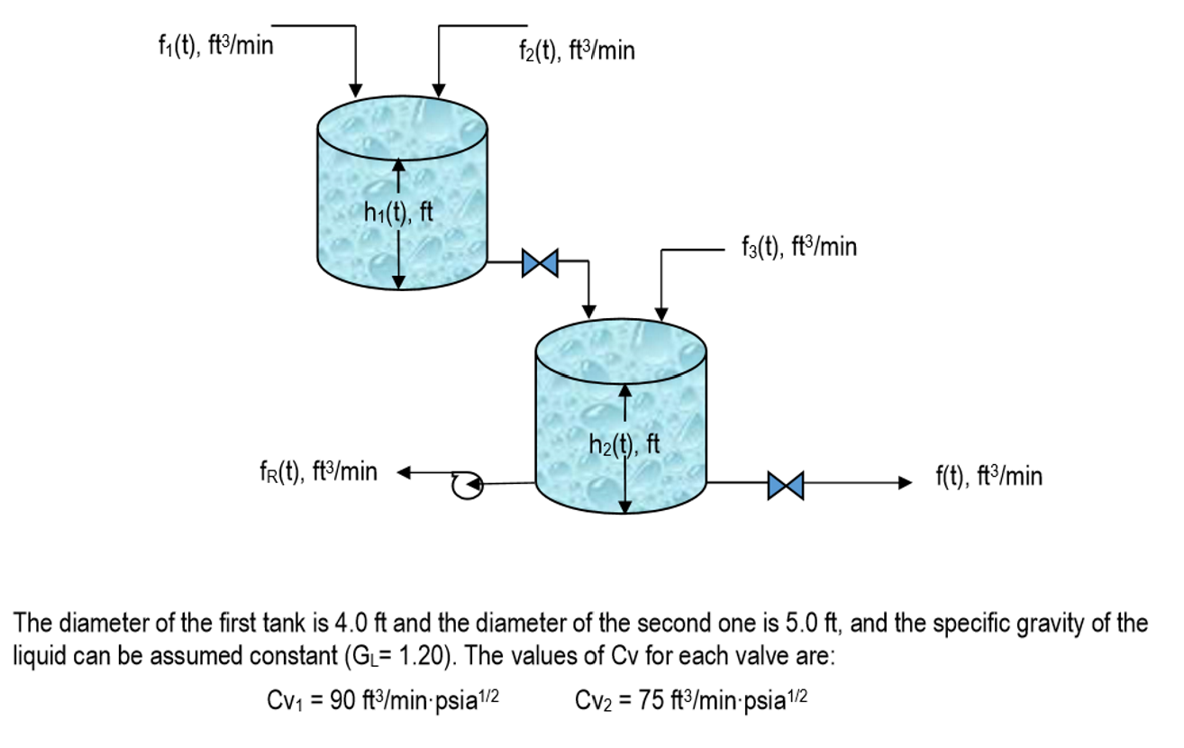
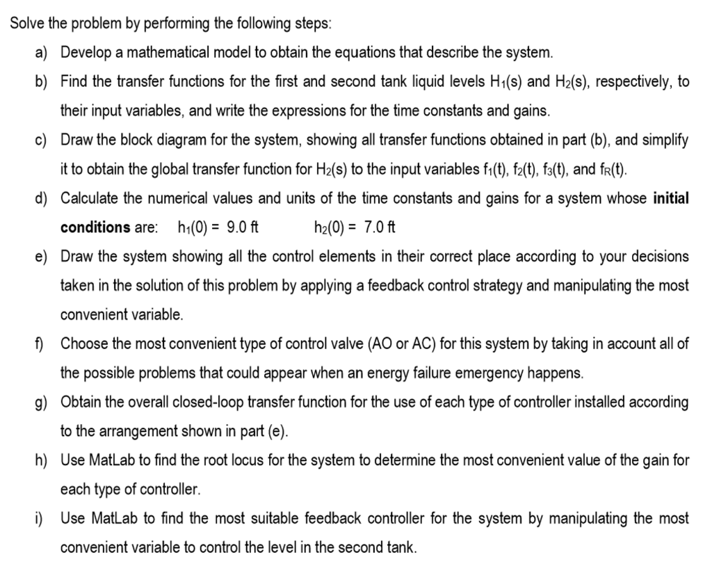
The diameter of the first tank is 4.0ft and the diameter of the second one is 5.0ft, and the specific gravity of the liquid can be assumed constant (GL=1.20). The values of Cv for each valve are: CV1=90ft/minpsia1/2CV2=75ft/minpsia1/2 Solve the problem by performing the following steps: a) Develop a mathematical model to obtain the equations that describe the system. b) Find the transfer functions for the first and second tank liquid levels H1(s) and H2(s), respectively, to their input variables, and write the expressions for the time constants and gains. c) Draw the block diagram for the system, showing all transfer functions obtained in part (b), and simplify it to obtain the global transfer function for H2(s) to the input variables f1(t),f2(t),f3(t), and fR(t). d) Calculate the numerical values and units of the time constants and gains for a system whose initial conditions are: h1(0)=9.0fth2(0)=7.0ft e) Draw the system showing all the control elements in their correct place according to your decisions taken in the solution of this problem by applying a feedback control strategy and manipulating the most convenient variable. f) Choose the most convenient type of control valve (AO or AC ) for this system by taking in account all of the possible problems that could appear when an energy failure emergency happens. g) Obtain the overall closed-loop transfer function for the use of each type of controller installed according to the arrangement shown in part (e). h) Use MatLab to find the root locus for the system to determine the most convenient value of the gain for each type of controller. i) Use MatLab to find the most suitable feedback controller for the system by manipulating the most The diameter of the first tank is 4.0ft and the diameter of the second one is 5.0ft, and the specific gravity of the liquid can be assumed constant (GL=1.20). The values of Cv for each valve are: CV1=90ft/minpsia1/2CV2=75ft/minpsia1/2 Solve the problem by performing the following steps: a) Develop a mathematical model to obtain the equations that describe the system. b) Find the transfer functions for the first and second tank liquid levels H1(s) and H2(s), respectively, to their input variables, and write the expressions for the time constants and gains. c) Draw the block diagram for the system, showing all transfer functions obtained in part (b), and simplify it to obtain the global transfer function for H2(s) to the input variables f1(t),f2(t),f3(t), and fR(t). d) Calculate the numerical values and units of the time constants and gains for a system whose initial conditions are: h1(0)=9.0fth2(0)=7.0ft e) Draw the system showing all the control elements in their correct place according to your decisions taken in the solution of this problem by applying a feedback control strategy and manipulating the most convenient variable. f) Choose the most convenient type of control valve (AO or AC ) for this system by taking in account all of the possible problems that could appear when an energy failure emergency happens. g) Obtain the overall closed-loop transfer function for the use of each type of controller installed according to the arrangement shown in part (e). h) Use MatLab to find the root locus for the system to determine the most convenient value of the gain for each type of controller. i) Use MatLab to find the most suitable feedback controller for the system by manipulating the most
Step by Step Solution
There are 3 Steps involved in it
Step: 1

Get Instant Access to Expert-Tailored Solutions
See step-by-step solutions with expert insights and AI powered tools for academic success
Step: 2

Step: 3
Ace Your Homework with AI
Get the answers you need in no time with our AI-driven, step-by-step assistance
Get Started
Introduction To Chemical Engineering Tools For Today And Tomorrow
Authors: Kenneth A. Solen, John N. Harb
5th Edition
0470885726, 978-0470885727