Answered step by step
Verified Expert Solution
Question
1 Approved Answer
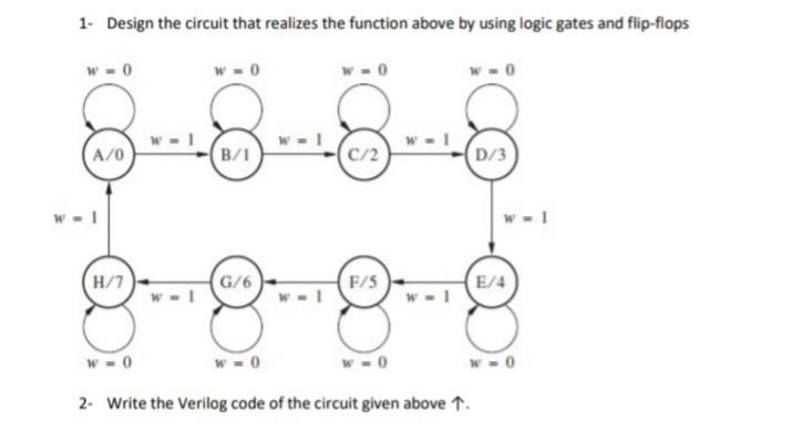
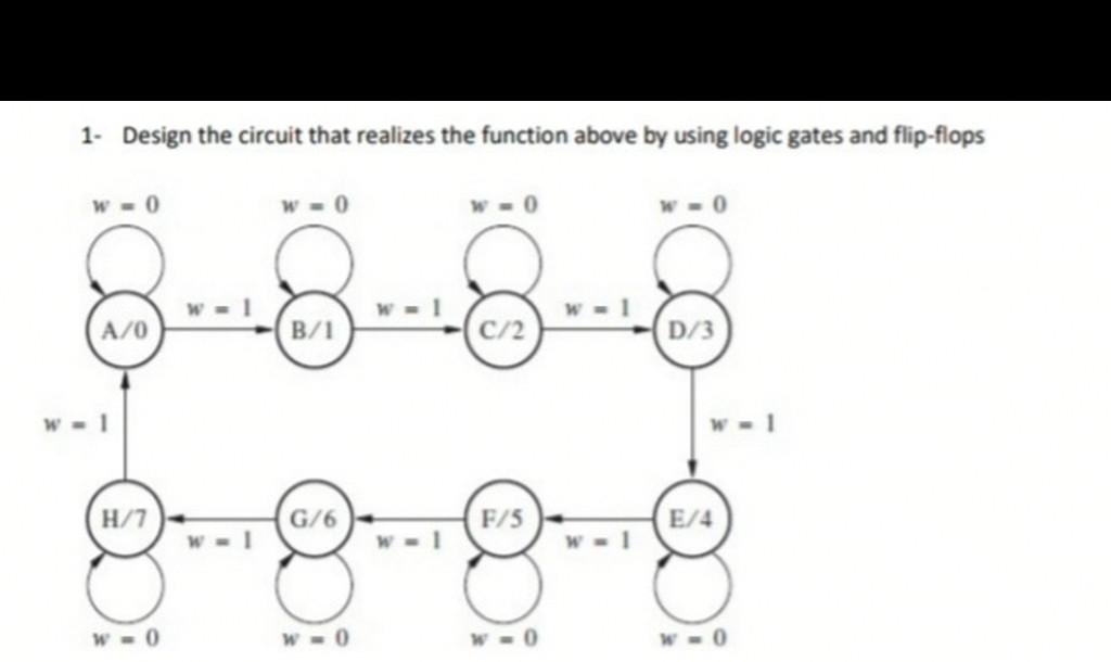
- Number 1&2 In The Photo 1. Design the circuit that realizes the function above by using logic gates and flip-flops B/1 C/2 D/3 W-1

 - Number 1&2 In The Photo

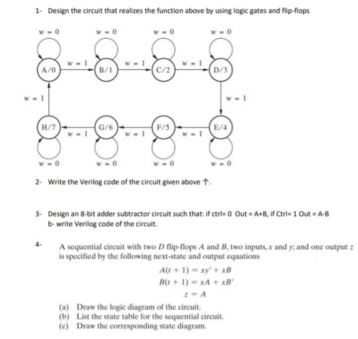
1. Design the circuit that realizes the function above by using logic gates and flip-flops B/1 C/2 D/3 W-1 H/7 G/6 F/5 E/4 W-1 W-0 W-0 W-0 2. Write the Verilog code of the circuit given above 1. 1. Design the circuit that realizes the function above by using logic gates and flip-flops 0 W-0 W = 0 S A/0 B/1 c/2 D/3 W-1 H/7 G/6 F/5 E/4 W-1 W-1 W-1 W-0 W-0 W-0 W-0 2. Write the Verilog code of the circuit given above 1. 3. Design an 8-bit adder subtractor circuit such that: if ctri= 0 Out = A+B, if Ctrl= 1 Out = A-B b- write Verilog code of the circuit. 4- A sequential circuit with two D flip-flops A and B two inputs, x and y, and one output z is specified by the following next-state and output equations A(1 + 1) = xy' + xB Bt + 1) = x+ + x3' (a) Draw the logic diagram of the circuit. (b) List the state table for the sequential circuit. (c) Draw the corresponding state diagram. 1. Design the circuit that realizes the function above by using logic gates and flip-flops w =0 A/0 (B/1 c/2 (D/3 H/7 0/6 F/5 E/4 w | w | w-I w w w 0 w
Step by Step Solution
There are 3 Steps involved in it
Step: 1

Get Instant Access to Expert-Tailored Solutions
See step-by-step solutions with expert insights and AI powered tools for academic success
Step: 2

Step: 3

Ace Your Homework with AI
Get the answers you need in no time with our AI-driven, step-by-step assistance
Get Started


