

Answered step by step
Verified Expert Solution
Question
1 Approved Answer
! ! ! ONLY HELP WITH PART B ! ! ! Guide on what should connect to what and how the circuit needs to run.
ONLY HELP WITH PART B Guide on what should connect to what and how the circuit needs to run. Task Description
For this assignment, you are required to implement a simple simulation of a
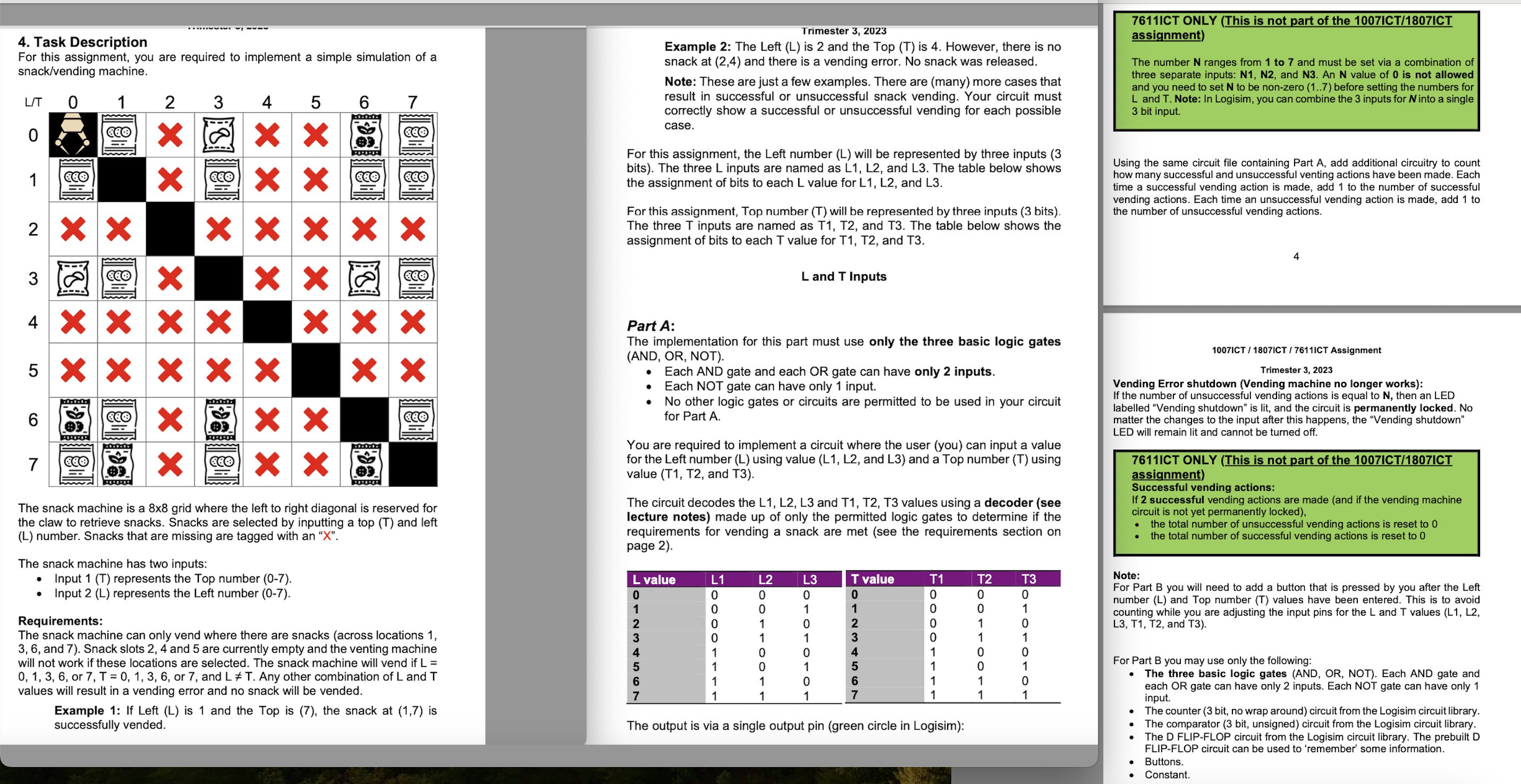
snackvending machine. The snack machine is a x grid where the left to right diagonal is reserved for
the claw to retrieve snacks. Snacks are selected by inputting a top T and left
L number. Snacks that are missing are tagged with an X
The snack machine has two inputs:
Input T represents the Top number
Input L represents the Left number
Requirements:
The snack machine can only vend where there are snacks across locations
and Snack slots and are currently empty and the venting machine
will not work if these locations are selected. The snack machine will vend if L
or T or and L T Any other combination of L and T
values will result in a vending error and no snack will be vended.
Example : If Left L is and the Top is the snack at is
successfully vended. Example : The Left L is and the Top T is However, there is no
snack at and there is a vending error. No snack was released.
Note: These are just a few examples. There are many more cases that
result in successful or unsuccessful snack vending. Your circuit must
correctly show a successful or unsuccessful vending for each possible
case.
For this assignment, the Left number L will be represented by three inputs
bits The three L inputs are named as L L and L The table below shows
the assignment of bits to each L value for L L and L
For this assignment, Top number T will be represented by three inputs bits
The three T inputs are named as T T and T The table below shows the
assignment of bits to each T value for T T and T
L and T Inputs. Part A:
The implementation for this part must use only the three basic logic gates
AND OR NOT
Each AND gate and each OR gate can have only inputs.
Each NOT gate can have only input.
No other logic gates or circuits are permitted to be used in your circuit
for Part A
You are required to implement a circuit where the user you can input a value
for the Left number L using value L L and L and a Top number T using
value T T and T
The circuit decodes the L L L and T T T values using a decoder see
lecture notes made up of only the permitted logic gates to determine if the
requirements for vending a snack are met see the requirements section on
page The output pin must be labelled Successful which is lit if L or T
or and L T The output pin is not lit for any other combination
values of L and T
Part B:
For this part, the snack machine has an alert mechanism that notifies the
vending machine company if a certain number N of unsuccessful vending
errors happen. People are pushing the wrong numbers either requesting lots
of missing snacks maybe the most popular snacks are missing or straining
the claw by requesting the locations the claw is using.
A vend error is when the snack machine tries to vend from an empty snack slot,
or if the vending input is in the same space as the claw eg L TThe number N ranges from to and must be set via a combination of
three separate inputs: N N and N An N value of is not allowed
and you need to set N to be nonzero before setting the numbers for
L and T Note: In LogisimUsing the same circuit file containing Part A add additional circuitry to coun
how many successful and unsuccessful venting actions have been made. Each
time a successful vending action is made, add to the number of successful
vending actions. Each time an unsuccessful vending action is made, add to
the number of unsuccessful vending actions. Vending Error shutdown Vending machine no longer works:
If the number of unsuccessful vending actions is equal to N then an LED
labelled Vending shutdown is lit, and the circuit is permanently locked. No
matter the changes to the input after this happens, the Vending shutdown
LED will remain lit and cannot be turned off. Successful vending actions:
If successful vending actions are made and if the vending machine
circuit is not yet permanently locked
the total number of unsuccessful vending actions is reset to
the total number of successful vending actions is reset to Note:
For Part B you will need to add a button that is pressed by you after the Left
number L and Top number T values have been entered. This is to avoid
counting while you are adjusting the input pins for the L and T values L L
L T T and T
For Part B you may use only the following:
The three basic logic gates AND OR NOT Each AND gate and
each OR gate can have only inputs. Each NOT gate can have only
input.
The counter bit, no wrap around circuit from the Logisim circuit library.
The comparator bit, un
Step by Step Solution
There are 3 Steps involved in it
Step: 1

Get Instant Access to Expert-Tailored Solutions
See step-by-step solutions with expert insights and AI powered tools for academic success
Step: 2

Step: 3
Ace Your Homework with AI
Get the answers you need in no time with our AI-driven, step-by-step assistance
Get Started
Mastering PostgreSQL 12 Advanced Techniques To Build And Administer Scalable And Reliable PostgreSQL Database Applications
Authors: Hans-Jurgen Schonig
3rd Edition
1838988823, 978-1838988821