Answered step by step
Verified Expert Solution
Question
1 Approved Answer
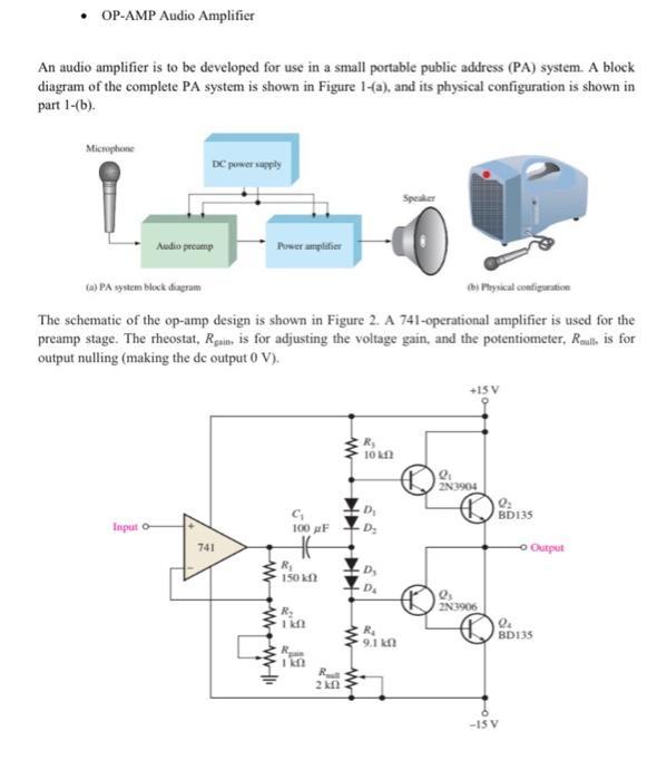
OP-AMP Audio Amplifier An audio amplifier is to be developed for use in a small portable public address (PA) system. A block diagram of


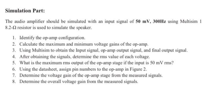
OP-AMP Audio Amplifier An audio amplifier is to be developed for use in a small portable public address (PA) system. A block diagram of the complete PA system is shown in Figure 1-(a), and its physical configuration is shown in part 1-(b). Microphone DC power supply Input o- Audio pecump Power amplifier (a) PA system block diagram (b) Physical configuration The schematic of the op-amp design is shown in Figure 2. A 741-operational amplifier is used for the preamp stage. The rheostat, Rain, is for adjusting the voltage gain, and the potentiometer, Rall, is for output nulling (making the de output 0 V). 741 www 100 F HE R 150 kf R 1 kft 1kf 2kf R 10 kf D D D Speaker R 9.1 kf +15 V Q 2N3904 Q 2N3906 Q BD135 -o Output la BD135 -15 V A partial datasheet for a 741 op-amp is shown in Figure 3. FAIRCHILD KA741 Single Operational Amplifier Features Internal Block Diagram Electrical Characteristics Offe interva AtRange put Of Curent Op Corne Output C Con M SC Power Consump Owrshad p Mo B VIOR-V af PAR T 481NU2 PREMAL Description AV VOL - STV VOC VORSTEY VOC VOL - TV PETO ALL YOMON 30 KLINI KING KANKAN M ac CHORE an 37 ww N 1113 COCCROCO 28 -ULLAR 1 . . 1-8211 Absolute Maximum Ratings (TA-25C) Electrical Characteristics THIMITS We TO MOST MC VIOWY W P NdV Tore Tyra 20 9220 MOYO+Y FO TOPP OPPTION * 115 300 0-70 84 45-150 KANINAN 112 a. 154 112 110113 10 71 NO 1 W 75 3 GODD V V Y - t -ELARA 4 1. M 1 Simulation Part: The audio amplifier should be simulated with an input signal of 50 mV, 300Hz using Multisim 1 8.2-2 resistor is used to simulate the speaker. 1. Identify the op-amp configuration. 2. Calculate the maximum and minimum voltage gains of the op-amp. 3. Using Multisim to obtain the Input signal, op-amp output signal, and final output signal. 4. After obtaining the signals, determine the rms value of each voltage. 5. What is the maximum rms output of the op-amp stage if the input is 50 mV rms? 6. Using the datasheet, assign pin numbers to the op-amp in Figure 2. 7. Determine the voltage gain of the op-amp stage from the measured signals. 8. Determine the overall voltage gain from the measured signals.
Step by Step Solution
★★★★★
3.44 Rating (163 Votes )
There are 3 Steps involved in it
Step: 1
1 The opamp configuration is a noninverting one 2Maximum ...
Get Instant Access to Expert-Tailored Solutions
See step-by-step solutions with expert insights and AI powered tools for academic success
Step: 2

Step: 3

Ace Your Homework with AI
Get the answers you need in no time with our AI-driven, step-by-step assistance
Get Started


