

Question: Our lesson is in the 3rd to 5th images. Please read the 3rd to 5th images for better understanding. WEEK 4 TLE 8 -Computer System
Our lesson is in the 3rd to 5th images. Please read the 3rd to 5th images for better understanding.
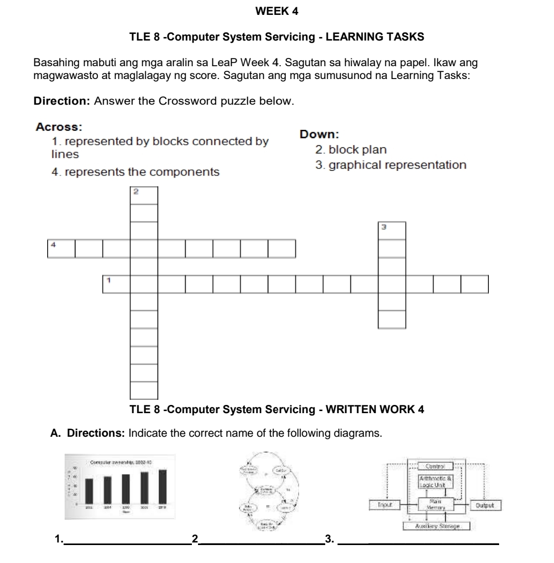
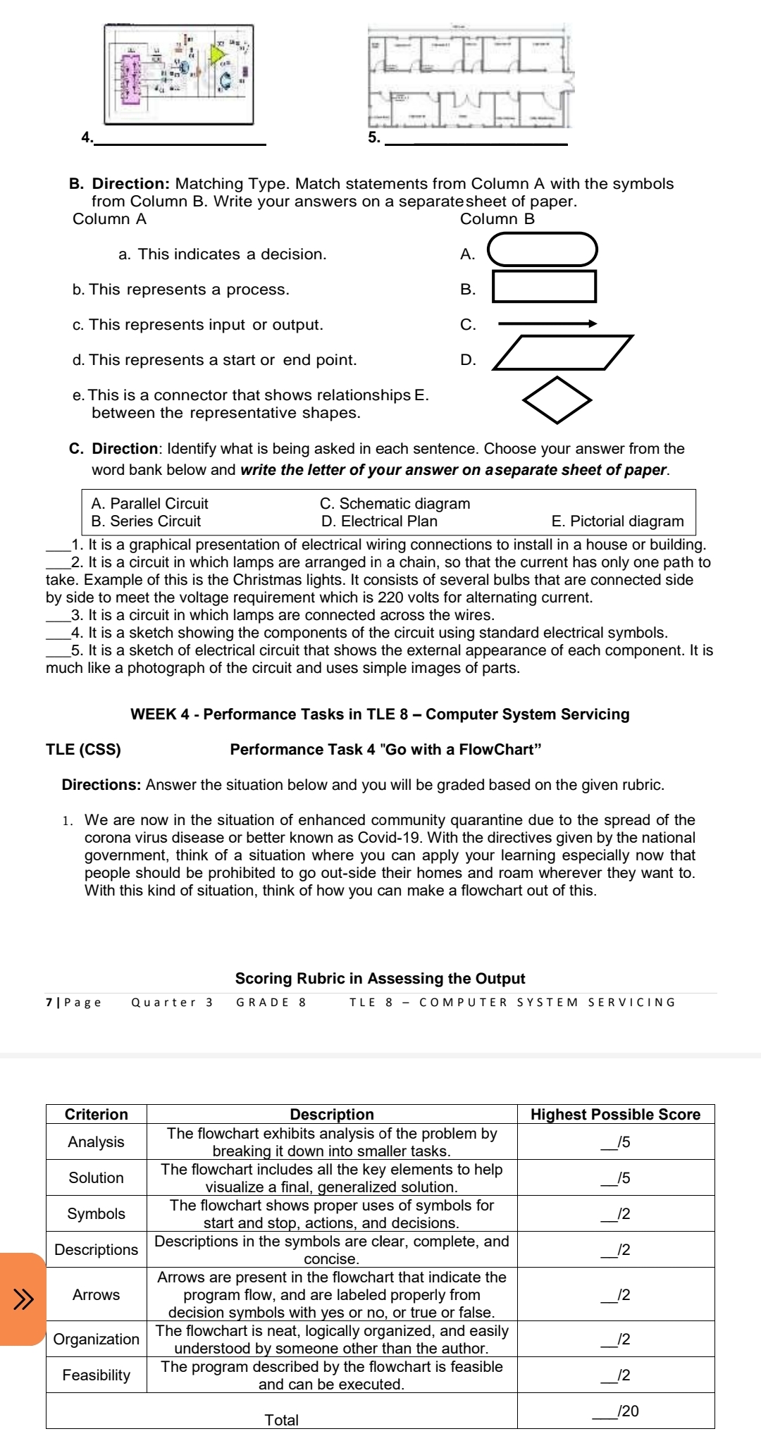
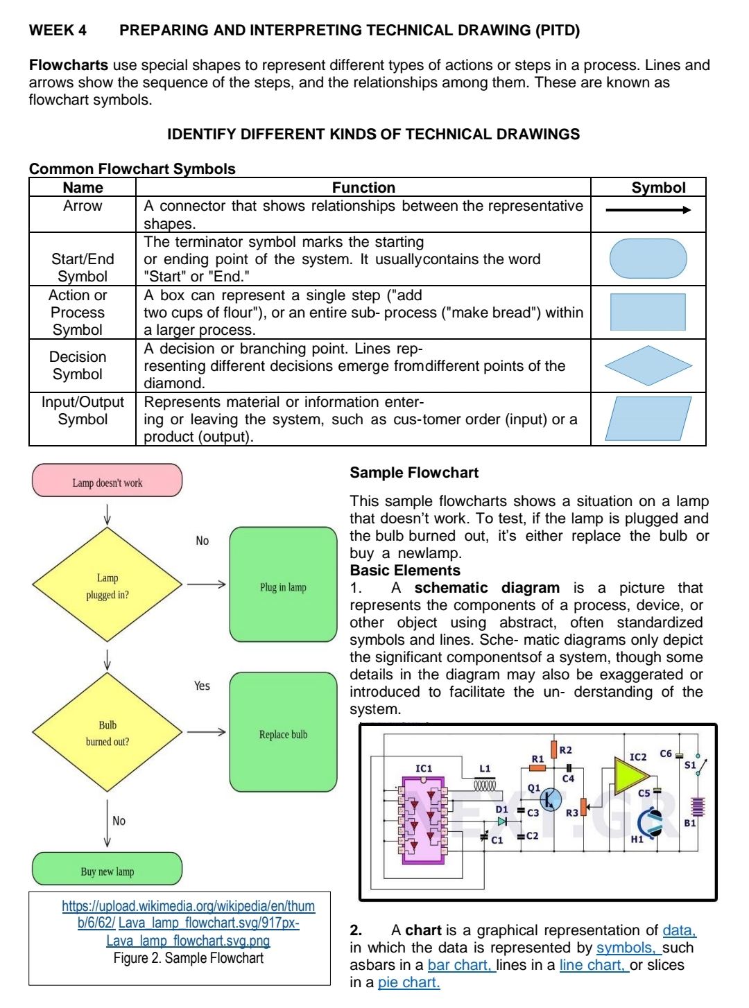
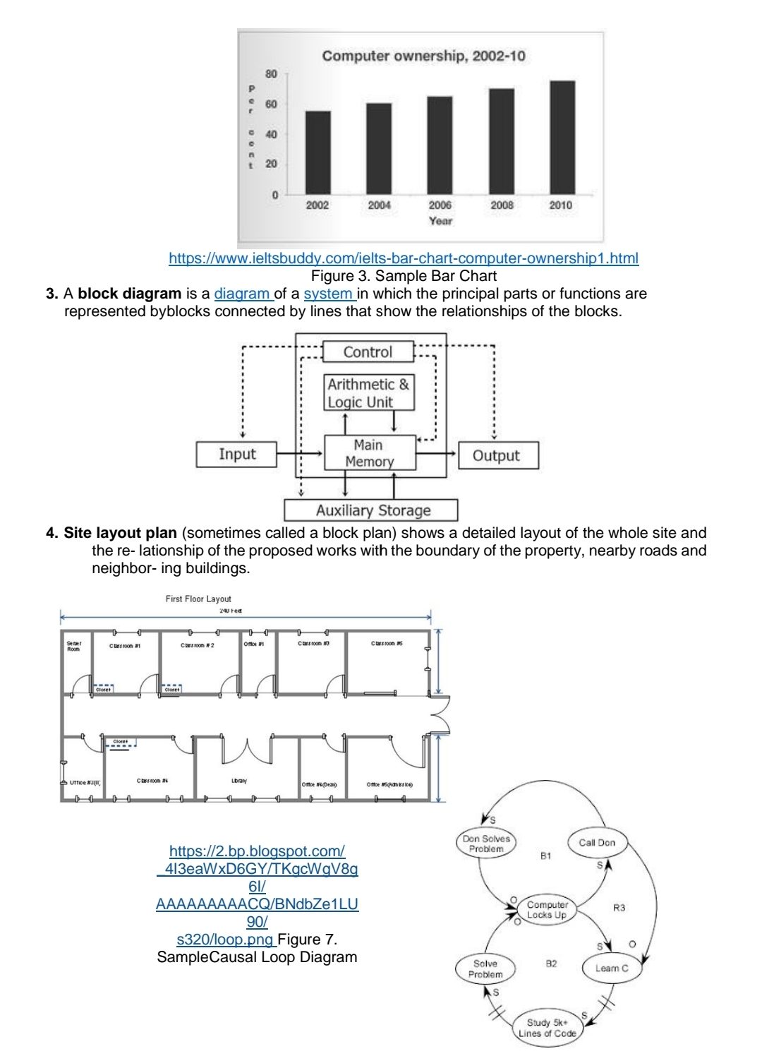
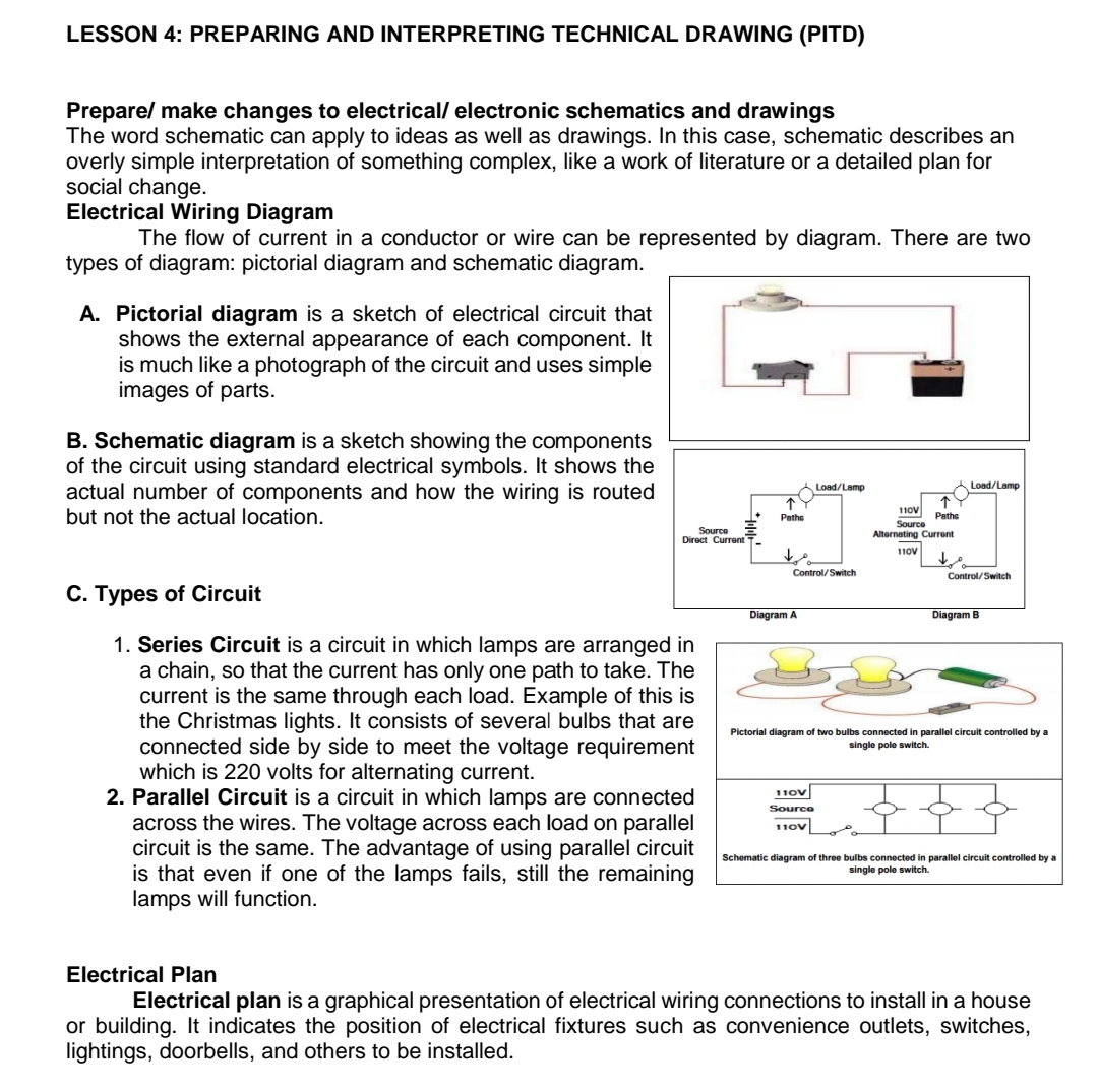
WEEK 4 TLE 8 -Computer System Servicing - LEARNING TASKS Basahing mabuti ang mga aralin sa Leap Week 4. Sagutan sa hiwalay na papel. Ikaw ang magwawasto at maglalagay ng score. Sagutan ang mga sumusunod na Learning Tasks: Direction: Answer the Crossword puzzle below. Across: 1. represented by blocks connected by Down: lines 2. block plan 3. graphical representation 4. represents the components 4 TLE 8 -Computer System Servicing - WRITTEN WORK 4 A. Directions: Indicate the correct name of the following diagrams. Control Artinmate & Logic Unt toour Output 3.B. Direction: Matching Type. Match statements from Column A with the symbols from Column B. Write your answers on a separate sheet of paper. Column A Column B a. This indicates a decision. A. b. This represents a process. B c. This represents input or output. C. D d. This represents a start or end point. e.This is a connector that shows relationships E. between the representative shapes. C. Direction: Identify what is being asked in each sentence. Choose your answer from the word bank below and write the letter of your answer on aseparate sheet of paper. A. Parallel Circuit 0. Schematic diagram B. Series Circuit D. Electrical Plan E. Pictorial diagram _'l. It is a graphical presentation of electrical wiring connections to install in a house or building. _2. It is a circuit in which lamps are arranged in a chain, so that the current has only one path to take. Example of this is the Christmas lights. It consists of several bulbs that are connected side by side to meet the voltage requirement which is 220 volts for alternating current. _3. It is a circuit in which lamps are connected across the wires. _4. It is a sketch showing the components of the circuit using standard electrical symbols. _5. It is a sketch of electrical circuit that shows the external appearance of each component. It is much like a photograph of the circuit and uses simple images of parts. WEEK 4 - Performance Tasks in TLE 8 - Computer System Servicing TLE ((285) Performance Task 4 "Go with a FlowChart" Directions: Answer the situation below and you will be graded based on the given rubric. 1. We are now in the situation of enhanced community quarantine clue to the spread of the corona virus disease or better known as Covid-19. With the directives given by the national government, think of a situation where you can apply your learning especially now that people should be prohibited to go out-side their homes and roam wherever they want to. With this kind of situation, think of how you can make a owchart out of this. Scoring Rubric in Assessing the Output 1|Page Quarter 3 GRADE 8 TLE 8COMPUTER SYSTEM SERVICING Criterion Description Highest Possible Score . The owchart exhibits analysis of the problem by AnalySIs breaking it down into smaller tasks. "5 Solution The owchart Includes all the key elements to help 15 Visualize a nal, generalized solution. The owchart shows proper uses of symbols for Symbols start and stop, actions, and decisions. I2 Descriptions Descriptions in the symbols are clear, complete, and I2 concrse. Arrows are present in the owchart that indicate the Arrows program ow, and are labeled properly from _i'2 decision symbols with yes or no, or true or false. . . The owchart is neat, logically organized, and easily Organization understood by someone other than the author. 12 Feasibility The program described by the owchart is feasrble 12 and can be executed. Total '20 WEEK 4 PREPARING AND INTERPRETING TECHNICAL DRAWING (PITD) Flowcharts use special shapes to represent different types of actions or steps in a process. Lines and arrows show the sequence of the steps, and the relationships among them. These are known as flowchart symbols. IDENTIFY DIFFERENT KINDS OF TECHNICAL DRAWINGS Common Flowchart S mbols Arrow A connector that shows relationships between the representative sha-es. The terminator symbol marks the starting Starthnd or ending point of the system. It usuallyoontains the word 8 mbol \"Start" or \"End.\" Action or A box can represent a single step ("add Process two cups of flour\"), or an entire sub process ("make bread") within S mbol Decision A decision or branching point. Lines rep- Symbol resenting different decisions emerge fromdifferent points of the diamond. Input/Output Represents material or information enter- Symbol ing or leaving the system, such as cus-tomer order (input) ora Sample Flowchart This sample flowcharts shows a situation on a lamp Jr that doesn't work. To test, if the lamp is plugged and No the bulb burned out, it's either replace the bulb or buy a newlamp. [mp Basic Elements > mum 1. A schematic diagram is a picture that represents the components of a process, device, or other object using abstract, often standardized symbols and lines. Sche- matic diagrams only depict J! the significant componentsof a system, though some details in the diagram may also be exaggerated or introduced to facilitate the un- derstanding of the system. Bulb binned out? httgflugloadwikimediaorglwikigdialenlthum mm\" lam OWChart'S\" '91? x' 2. A chart is a graphical representation of data, Lava I m w h ' V ' n in which the data is represented by symbols, such Figure 2- samp'e \"mm\" asbars in a bar chart lines in a line chart or slices in a Qie chart. Computer ownership, 2002-10 BO 60 40 20 2002 2004 200 2008 2010 Year https://www.ieltsbuddy.com/ielts-bar-chart-computer-ownership1.html Figure 3. Sample Bar Chart 3. A block diagram is a diagram of a system in which the principal parts or functions are represented byblocks connected by lines that show the relationships of the blocks. Control Arithmetic & Logic Unit Main Input Memory Output Auxiliary Storage 4. Site layout plan (sometimes called a block plan) shows a detailed layout of the whole site and the re- lationship of the proposed works with the boundary of the property, nearby roads and neighbor- ing buildings. First Floor Layout 240 ree Chersoon 24 Don Solves https://2.bp.blogspot.com/ Problem Call Don B1 413eaWxD6GY/TKgcWqV8q S 61/ AAAAAAAAACQ/BNdbZe1LU Computer R3 Locks Up 90/ O $320/loop.png_Figure 7. Sample Causal Loop Diagram Solve 82 Learn C Problem Study 5k+ Lines of CodeLESSON 4: PREPARING AND INTERPRETING TECHNICAL DRAWING (PITD) Prepare/ make changes to electrical/ electronic schematics and drawings The word schematic can apply to ideas as well as drawings. In this case, schematic describes an overly simple interpretation of something complex, like a work of literature or a detailed plan for social change. Electrical Wiring Diagram The flow of current in a conductor or wire can be represented by diagram. There are two types of diagram: pictorial diagram and schematic diagram. A. Pictorial diagram is a sketch of electrical circuit that shows the external appearance of each component. It is much like a photograph of the circuit and uses simple images of parts. B. Schematic diagram is a sketch showing the components of the circuit using standard electrical symbols. It shows the actual number of components and how the wiring is routed Load/Lamp Load/Lamp but not the actual location. 1 10V Paths Source Direct Currant Alternating Current Control/Switch Control/Switch C. Types of Circuit Diagram A Diagram B 1. Series Circuit is a circuit in which lamps are arranged in a chain, so that the current has only one path to take. The current is the same through each load. Example of this is the Christmas lights. It consists of several bulbs that are Pictorial diagram of two bulbs connected in parallel circuit controlled by a connected side by side to meet the voltage requirement single pole switch. which is 220 volts for alternating current. 2. Parallel Circuit is a circuit in which lamps are connected 1 10V Source across the wires. The voltage across each load on parallel circuit is the same. The advantage of using parallel circuit Schematic diagram of three bulbs connected in parallel circuit controlled by a is that even if one of the lamps fails, still the remaining single pole switch. lamps will function. Electrical Plan Electrical plan is a graphical presentation of electrical wiring connections to install in a house or building. It indicates the position of electrical fixtures such as convenience outlets, switches, lightings, doorbells, and others to be installed
Step by Step Solution
There are 3 Steps involved in it

Get step-by-step solutions from verified subject matter experts