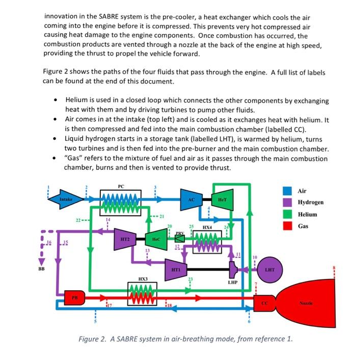
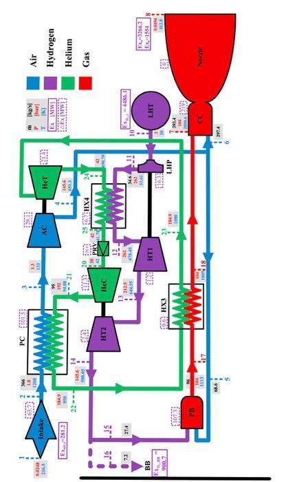
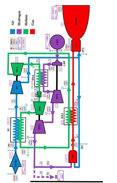
Over the past ten years, the Synergetic Air-Breathing Rocket Engine (SABRE) has been in development by Reaction Engines Limited. It is intended as a single stage system for transporting payloads into low Earth orbit, fuelled by liquid hydrogen. Below an altitude of about 28 km, the engine is air-breathing (hence the name), feeding compressed and cooled air from the atmosphere into the combustion chamber in an open cycle. This is similar to a conventional turbojet engine. Beyond that altitude and at speeds above Mach 5.5), the engine switches to a closed cycle using stored liquid oxygen as the oxidiser. The critical innovation in the SABRE system is the pre-cooler, a heat exchanger which cools the air coming into the engine before it is compressed. This prevents very hot compressed air causing heat damage to the engine components. Once combustion has occurred, the combustion products are vented through a nozzle at the back of the engine at high speed, providing the thrust to propel the vehicle forward. Figure 2 shows the paths of the four fluids that pass through the engine. A full list of labels can be found at the end of this document. Helium is used in a closed loop which connects the other components by exchanging heat with them and by driving turbines to pump other fluids. Air comes in at the intake (top left) and is cooled as it exchanges heat with helium. It is then compressed and fed into the main combustion chamber (labelled CC). Liquid hydrogen starts in a storage tank (labelled LHT), is warmed by helium, turns two turbines and is then fed into the pre-burner and the main combustion chamber. "Gas refers to the mixture of fuel and air as it passes through the main combustion chamber, burns and then is vented to provide thrust. PC Air Intake Hydrogen Helium Gas HX4 HT2 JS BB HTI HX3 LHP FA Nonne Figure 2. A SABRE system in air-breathing mode, from reference 1. We recommend that you spend some time familiarising yourself with this diagram, and following the pathways for each fluid. Then look at Figure 3. This is the same diagram, but specific temperatures and pressures are shown at different locations within the engine. PC 101 366 IN 100 m 00345 2165 har Intake AC 1 Exa/281.2 EX IMWI AEIMWI Air Hydrogen Helium Gas 21 145.6 613 145.6 S. 2567 HX4 HT2 Hec 15 7.2 2115 362 3361 BB Ex 1554 . 14 2006 EXH LHP 1934 219 104 1113 More 297.4 Questions 1.(a) Draw a simplified diagram of the engine suitable for a control volume analysis of the thrust. Make sure that all relevant parameters are labelled on the diagram. Write out the full version of the momentum equation and briefly describe how each term in the equation relates to the physical engine. (b) The engine is being tested in a controlled-atmosphere wind tunnel which matches the conditions at 20 km altitude and a speed of Mach 4. The engineers measure the thrust from the engine burning steadily and find that it is 2.5 X 10N. Use the momentum equation and the data given below to estimate the speed of the exhaust gas leaving the engine, explaining the logic behind each step. Air is entering the engine at Mach 4, since the engine would meet undisturbed air at that speed. The speed of sound at this altitude is 295 m/s. Assume that the P and T data at points 1 and 8 in figure 3 apply here, and take inflow and outflow mass flow rate m from points 2 and 7. Assume that the cross-sectional areas of the inlet and outlet are 5 m and 1.5 m respectively. You may assume that all the air enters at a uniform speed and exits with another uniform speed. The thrust is equal in magnitude to the anchoring force needed to hold the engine in place. 2. Use the concepts relevant to gas power cycles for developing a simplified thermodynamic cycles for analysing the performance of the engine. The following assumptions could be considered: The helium loop works on a closed Brayton cycle, and the air-breathing engine works on an open Brayton cycle. These can be analysed separately. The heat exchangers all work at constant pressure (if different input and output pressures are shown, take the average to find the constant pressure). Consider the expansion and compression processes in the components such as nozzle, compressors and turbines to be isentropic. To answer the questions below, use the data shown in Figure 3. (a) Reconstruct the Helium Loop (shown in green in figures 2 and 3) using the above assumptions and calculate its thermal efficiency, (b) Convert the open cycle on which the engine operates to an equivalent closed cycle for your analysis. The key components that form the open cycle of the engine (excluding the hydrogen tank and the pre-burner) are represented by states 1-2-3-4-6-7-8 in figure 3. Draw a diagram and explain all the stages in the cycle. (c) Calculate the thermal efficiency of the equivalent closed cycle you described in part (b). PC 101 366 IN 100 m 00345 2165 har Intake AC 1 Exa/281.2 EX IMWI AEIMWI Air Hydrogen Helium Gas 21 145.6 613 145.6 S. 2567 HX4 HT2 Hec 15 7.2 2115 362 3361 BB Ex 1554 . 14 2006 EXH LHP 1934 219 104 1113 More 297.4 Over the past ten years, the Synergetic Air-Breathing Rocket Engine (SABRE) has been in development by Reaction Engines Limited. It is intended as a single stage system for transporting payloads into low Earth orbit, fuelled by liquid hydrogen. Below an altitude of about 28 km, the engine is air-breathing (hence the name), feeding compressed and cooled air from the atmosphere into the combustion chamber in an open cycle. This is similar to a conventional turbojet engine. Beyond that altitude and at speeds above Mach 5.5), the engine switches to a closed cycle using stored liquid oxygen as the oxidiser. The critical innovation in the SABRE system is the pre-cooler, a heat exchanger which cools the air coming into the engine before it is compressed. This prevents very hot compressed air causing heat damage to the engine components. Once combustion has occurred, the combustion products are vented through a nozzle at the back of the engine at high speed, providing the thrust to propel the vehicle forward. Figure 2 shows the paths of the four fluids that pass through the engine. A full list of labels can be found at the end of this document. Helium is used in a closed loop which connects the other components by exchanging heat with them and by driving turbines to pump other fluids. Air comes in at the intake (top left) and is cooled as it exchanges heat with helium. It is then compressed and fed into the main combustion chamber (labelled CC). Liquid hydrogen starts in a storage tank (labelled LHT), is warmed by helium, turns two turbines and is then fed into the pre-burner and the main combustion chamber. "Gas refers to the mixture of fuel and air as it passes through the main combustion chamber, burns and then is vented to provide thrust. PC Air Intake Hydrogen Helium Gas HX4 HT2 JS BB HTI HX3 LHP FA Nonne Figure 2. A SABRE system in air-breathing mode, from reference 1. We recommend that you spend some time familiarising yourself with this diagram, and following the pathways for each fluid. Then look at Figure 3. This is the same diagram, but specific temperatures and pressures are shown at different locations within the engine. PC 101 366 IN 100 m 00345 2165 har Intake AC 1 Exa/281.2 EX IMWI AEIMWI Air Hydrogen Helium Gas 21 145.6 613 145.6 S. 2567 HX4 HT2 Hec 15 7.2 2115 362 3361 BB Ex 1554 . 14 2006 EXH LHP 1934 219 104 1113 More 297.4 Questions 1.(a) Draw a simplified diagram of the engine suitable for a control volume analysis of the thrust. Make sure that all relevant parameters are labelled on the diagram. Write out the full version of the momentum equation and briefly describe how each term in the equation relates to the physical engine. (b) The engine is being tested in a controlled-atmosphere wind tunnel which matches the conditions at 20 km altitude and a speed of Mach 4. The engineers measure the thrust from the engine burning steadily and find that it is 2.5 X 10N. Use the momentum equation and the data given below to estimate the speed of the exhaust gas leaving the engine, explaining the logic behind each step. Air is entering the engine at Mach 4, since the engine would meet undisturbed air at that speed. The speed of sound at this altitude is 295 m/s. Assume that the P and T data at points 1 and 8 in figure 3 apply here, and take inflow and outflow mass flow rate m from points 2 and 7. Assume that the cross-sectional areas of the inlet and outlet are 5 m and 1.5 m respectively. You may assume that all the air enters at a uniform speed and exits with another uniform speed. The thrust is equal in magnitude to the anchoring force needed to hold the engine in place. 2. Use the concepts relevant to gas power cycles for developing a simplified thermodynamic cycles for analysing the performance of the engine. The following assumptions could be considered: The helium loop works on a closed Brayton cycle, and the air-breathing engine works on an open Brayton cycle. These can be analysed separately. The heat exchangers all work at constant pressure (if different input and output pressures are shown, take the average to find the constant pressure). Consider the expansion and compression processes in the components such as nozzle, compressors and turbines to be isentropic. To answer the questions below, use the data shown in Figure 3. (a) Reconstruct the Helium Loop (shown in green in figures 2 and 3) using the above assumptions and calculate its thermal efficiency, (b) Convert the open cycle on which the engine operates to an equivalent closed cycle for your analysis. The key components that form the open cycle of the engine (excluding the hydrogen tank and the pre-burner) are represented by states 1-2-3-4-6-7-8 in figure 3. Draw a diagram and explain all the stages in the cycle. (c) Calculate the thermal efficiency of the equivalent closed cycle you described in part (b). PC 101 366 IN 100 m 00345 2165 har Intake AC 1 Exa/281.2 EX IMWI AEIMWI Air Hydrogen Helium Gas 21 145.6 613 145.6 S. 2567 HX4 HT2 Hec 15 7.2 2115 362 3361 BB Ex 1554 . 14 2006 EXH LHP 1934 219 104 1113 More 297.4


