Part 1: 1} 2} 3} 4} 5} *5} T} 3} Write a code to initialize GPIGl l5 and GPID41-GPIU43 [for motor control}, GPIDSI [L132], and
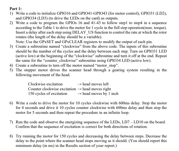
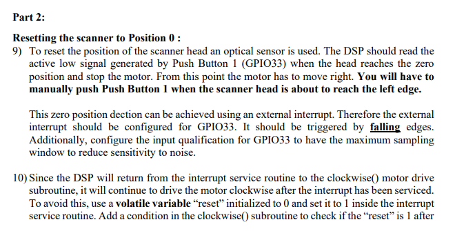
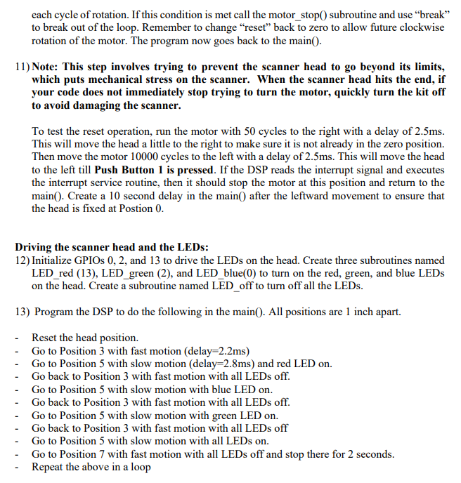
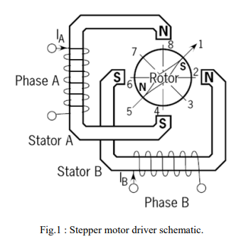
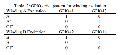
Part 1: 1} 2} 3} 4} 5} *5} T} 3} Write a code to initialize GPIGl l5 and GPID41-GPIU43 [for motor control}, GPIDSI [L132], and GPIDB4 (L133) [to drive the LEDs on the card] as outputs. Write a code to program the GPIDs 16 and 41-43 to follow stepl to slept in a sequence according to the Table l to drive the motor for 1 cycle in the full step operation{max. torque]. Insert a delay after each step using DELAY_US function to control the rate at which the rotor rotates [the length of the delay should be a variable). Note: Use the GPxSET and GPxCLEAR registers to modify the output of each pin. Create a subroutine named \"clockwise" from the above code. The inputs of this subroutine should be the nUmber of the cycles and the delay between each step. Turn on GPIDBI LED {active low] at the beginning of the \"clockwise\" subroutine and turn it off at the and. Repeat the same for the \"counter_clockwise\" subroutine Using GPIDS4 LED {active low]. Create a subroutine to turn off the motor named \"motor_stop\". The stepper motor drives the scanner head through a gearing system resulting in the following movement of the head. Clockwise excitation r head moves left Counter clockwise excitation r head moves right 15!] cycles of excitation r head moves by 1 inch Write a code to drive the motor for It} cycles clockwise with ms delay. Stop the motor for 4 seconds and drive it It) cycles counter clockwise with oDms delay and then stop the motor for 5 seconds and then repeat the procedure in an innite loop. Run the code and observe the energizing sequence of the LEDs, L13\"?Ir LI) It] on the board. Conrm that the sequence of excitation is correct for both directions of rotation. Try running the motor for Lil] cycles and decreasing the delay between steps. Decrease the delay to the point where the scanner head stops moving as it should. [You should rcport this minimum delay (in ms) in the Results section of your report} Part 2: Resetting the scanner to Position ll : 9'} To reset the position of the scannEr head an optical sensor is used. The DSP should read the active low signal generated by sh Button 1 (GP1033} when the head reaches the zero position and stop the motor. From this point the motor has to move right. You 1will have m manually push Push Button 1 when the sennner head is about to reach the left edge. This zero position dection can be achieved using an external intennpt. Therefore the external interruPt should be congured for GPIDSS. It should be triggered by falling edges. Additionally. congure the input qualication for GPIDBE to have the maximum sampling window to reduce sensitivity to noise. I'll} Since the DSP' will return from the interrupt service routine to the clockwise motor drive subroutine, it will continue to drive the motor clockwise after the interrupt has been serviced. To avoid this, use a volatile variable \"reset\" initialized to [l and set it to 1 inside the interrupt service routine. Add a condition in the clockwise subroutine to check if the \"reset\" is 1 after each cycle of rotation. If this condition is met call the motor_stop0 subroutine and use \"break" to break out of the loop. Remember to change \"reset\" back to acre to allow iture clockwise rotation ofthe motor. The program now goes back to the main(}. lleete: This step involves trying to prevent the scanner head to go beyond its limits, which puts mechanical stress on the scanner. 1When the scanner head hits the end, if your code does not immediately stop trying to turn the motor, quickly turn the kit off to avoid damaging the scanner. To [cst the reset operation, nm the motor with 51'] cycles to the right with a delay of 2.5ms. This will move the head a little to the right to make sure it is not already in the Zero position. Then move the motor l cycles to the left. with a delay of 2.5ms. This will move the head to the left till Push Button 1 is pressed. If the DSP reads the interrupt signal and executes the interrupt service routine, than it should stop the motor at this position and return to the maimf). Create a It} semnd delay in the main(} after the leftward movement to more that the head is fixed at Postion ll. Driving the scanner head and the LEDs: 12) Initialize GPIDs Ill, 2, and [3 to drive the LEDs on the head. Create three subroutines named LED_red {l3}. LED _green (2), and LED_blue(II}) to turn on the red, green. and blue LEDs on the head. Create a subroutine named LED_off to turn off all the LEDs. 13) Program the DSP to do the following in the main{]. All positions are l inch apart. - Reset the head position. - Go to Position 3 with fast motion {delay=2.2ms} - Go to Position 5 with slow motion {delay=2.Ems) and red LED on. - Go back to Position 3 with fast motion with all LEDs off. - Go to Position 5 with slow motion with blue LED on. - Go back to Position 3 with fast motion with all LEDs off. - Go to Position 5 with slow motion with green LED on. - Go back to Position 3 with fast motion with all LEDs off - Go to Position 5 with slow motion with all LEDs on. - Go to Position 7 with fast motion with all LEDs off and stop there for 2 seconds. - Repeat the above in a loop N O S Phase A S Rotor N N 3 S Stator A Stator B B O Phase B Fig.1 : Stepper motor driver schematic.\f
Step by Step Solution
There are 3 Steps involved in it
Step: 1
Get Instant Access to Expert-Tailored Solutions
See step-by-step solutions with expert insights and AI powered tools for academic success
Step: 2
Step: 3
Ace Your Homework with AI
Get the answers you need in no time with our AI-driven, step-by-step assistance