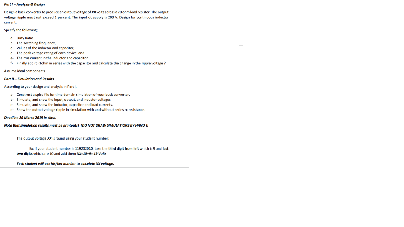
Part 1 - Analysis & Design Design a buck converter to produce an output voltage of XX volts across a 20 ohm load resistor. The output voltage ripple must not exceed 1 percent. The input dc supply is 200 V. Design for continuous inductor current. Specify the following; a Duty Ratio b- The switching frequency, C Values of the inductor and capacitor, e- The rms current in the inductor and capacitor. f. Finally add rc=10hm in series with the capacitor and calculate the change in the ripple voltage ? Assume ideal components. Part II - Simulation and Results According to your design and analysis in Part I, a. Construct a spice file for time domain simulation of your buck converter. b- Simulate, and show the input, output, and inductor voltages C. Simulate, and show the inductor, capacitor and load currents. d- Show the output voltage ripple in simulation with and without series rc resistance. Deadline 20 March 2019 in class. Note that simulation results must be printouts! (DO NOT DRAW SIMULATIONS BY HAND !) The output voltage XX is found using your student number: Ex: If your student number is 119202010, take the third digit from left which is 9 and last two digits which are 10 and add them XX=10+9= 19 Volts Each student will use his/her number to calculate XX voltage. Part 1 - Analysis & Design Design a buck converter to produce an output voltage of XX volts across a 20 ohm load resistor. The output voltage ripple must not exceed 1 percent. The input dc supply is 200 V. Design for continuous inductor current. Specify the following; a Duty Ratio b- The switching frequency, C Values of the inductor and capacitor, e- The rms current in the inductor and capacitor. f. Finally add rc=10hm in series with the capacitor and calculate the change in the ripple voltage ? Assume ideal components. Part II - Simulation and Results According to your design and analysis in Part I, a. Construct a spice file for time domain simulation of your buck converter. b- Simulate, and show the input, output, and inductor voltages C. Simulate, and show the inductor, capacitor and load currents. d- Show the output voltage ripple in simulation with and without series rc resistance. Deadline 20 March 2019 in class. Note that simulation results must be printouts! (DO NOT DRAW SIMULATIONS BY HAND !) The output voltage XX is found using your student number: Ex: If your student number is 119202010, take the third digit from left which is 9 and last two digits which are 10 and add them XX=10+9= 19 Volts Each student will use his/her number to calculate XX voltage