

Question: PLEASE ANSWER ONLY NUMBER 2! I HAVE PROVIDED THE WHOLE INSTRUCTIONS JUST TO HELP Work all of the problems. In order to give you faster
PLEASE ANSWER ONLY NUMBER 2! I HAVE PROVIDED THE WHOLE INSTRUCTIONS JUST TO HELP
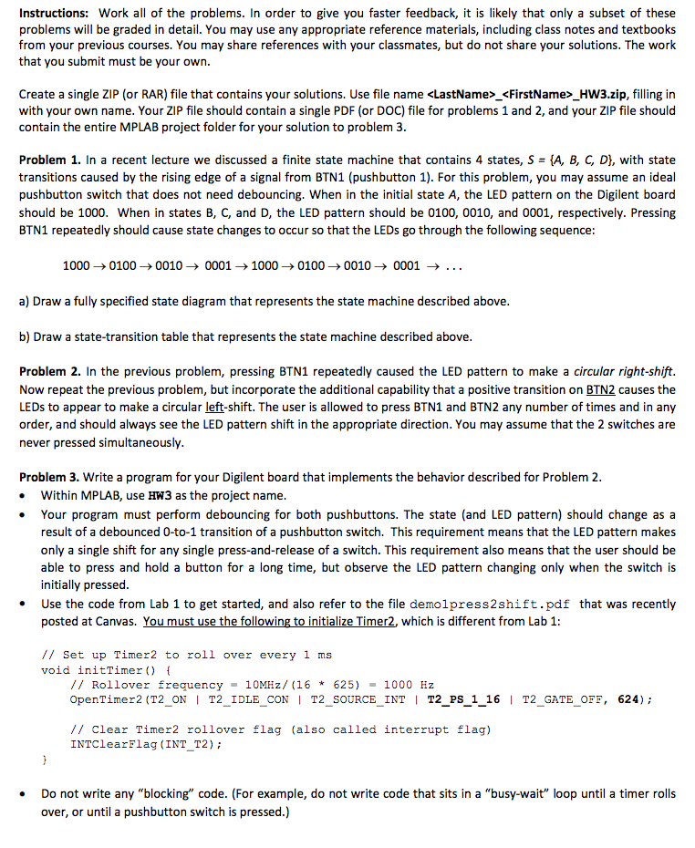
Work all of the problems. In order to give you faster feedback, it is likely that only a subset of these problems will be graded in detail. You may use any appropriate reference materials, including class notes and textbooks from your previous courses. You may share references with your classmates, but do not share your solutions. The work that you submit must be your own. Create a single ZIP (or RAR) file that contains your solutions. Use file name _ _HW3.zip, filling in with your own name. Your ZIP file should contain a single PDF (or DOC) file for problems 1 and 2, and your ZIP file should contain the entire MPLAB project folder for your solution to problem 3. In a recent lecture we discussed a finite state machine that contains 4 states, S = {A, B, C, D}, with state transitions caused by the rising edge of a signal from BTN1 (pushbutton 1). For this problem, you may assume an ideal pushbutton switch that does not need debouncing. When in the initial state A, the LED pattern on the Digilent board should be 1000. When in states B, C, and D, the LED pattern should be 0100,0010, and 0001, respectively. Pressing BTN1 repeatedly should cause state changes to occur so that the LEDs go through the following sequence: 1000 rightarrow 0100 rightarrow 0010 rightarrow 0001 rightarrow 1000 rightarrow 0100 rightarrow 0010 rightarrow 0001 rightarrow .. a) Draw a fully specified state diagram that represents the state machine described above. b) Draw a state-transition table that represents the state machine described above. In the previous problem, pressing BTN1 repeatedly caused the LED pattern to make a circular right-shift. Now repeat the previous problem, but incorporate the additional capability that a positive transition on BTN2 causes the LEDs to appear to make a circular left-shift. The user is allowed to press BTN1 and BTN2 any number of times and in any order, and should always see the LED pattern shift in the appropriate direction. You may assume that the 2 switches are never pressed simultaneously. Write a program for your Digilent board that implements the behavior described for Problem 2. Within MPLAB, use HW3 as the project name. Your program must perform debouncing for both pushbuttons. The state (and LED pattern) should change as a result of a debounced 0-to-1 transition of a pushbutton switch. This requirement means that the LED pattern makes only a single shift for any single press-and-release of a switch. This requirement also means that the user should be able to press and hold a button for a long time, but observe the LED pattern changing only when the switch is initially pressed. Use the code from Lab 1 to get started, and also refer to the file demolpress2shift pdf that was recently posted at Canvas. You must use the following to initialize Timer2. which is different from Lab 1: // Set up Timer2 to roll over every 1 ms void initTimer() { // Rollover frequency = 10MKz/(16 * 625) = 1000 Hz OpenTimer2(T2_ON | T2_IDLE_CON | T2_SOURCE_INT | T2_PS_1_16 | T2_GATE_OFF, 624): // Clear Timer2 rollover flag (also called interrupt flag) INTClearFlag(INT_T2): } Do not write any "blocking" code. (For example, do not write code that sits in a "busy-wait" loop until a timer rolls over, or until a pushbutton switch is pressed.) Work all of the problems. In order to give you faster feedback, it is likely that only a subset of these problems will be graded in detail. You may use any appropriate reference materials, including class notes and textbooks from your previous courses. You may share references with your classmates, but do not share your solutions. The work that you submit must be your own. Create a single ZIP (or RAR) file that contains your solutions. Use file name _ _HW3.zip, filling in with your own name. Your ZIP file should contain a single PDF (or DOC) file for problems 1 and 2, and your ZIP file should contain the entire MPLAB project folder for your solution to problem 3. In a recent lecture we discussed a finite state machine that contains 4 states, S = {A, B, C, D}, with state transitions caused by the rising edge of a signal from BTN1 (pushbutton 1). For this problem, you may assume an ideal pushbutton switch that does not need debouncing. When in the initial state A, the LED pattern on the Digilent board should be 1000. When in states B, C, and D, the LED pattern should be 0100,0010, and 0001, respectively. Pressing BTN1 repeatedly should cause state changes to occur so that the LEDs go through the following sequence: 1000 rightarrow 0100 rightarrow 0010 rightarrow 0001 rightarrow 1000 rightarrow 0100 rightarrow 0010 rightarrow 0001 rightarrow .. a) Draw a fully specified state diagram that represents the state machine described above. b) Draw a state-transition table that represents the state machine described above. In the previous problem, pressing BTN1 repeatedly caused the LED pattern to make a circular right-shift. Now repeat the previous problem, but incorporate the additional capability that a positive transition on BTN2 causes the LEDs to appear to make a circular left-shift. The user is allowed to press BTN1 and BTN2 any number of times and in any order, and should always see the LED pattern shift in the appropriate direction. You may assume that the 2 switches are never pressed simultaneously. Write a program for your Digilent board that implements the behavior described for Problem 2. Within MPLAB, use HW3 as the project name. Your program must perform debouncing for both pushbuttons. The state (and LED pattern) should change as a result of a debounced 0-to-1 transition of a pushbutton switch. This requirement means that the LED pattern makes only a single shift for any single press-and-release of a switch. This requirement also means that the user should be able to press and hold a button for a long time, but observe the LED pattern changing only when the switch is initially pressed. Use the code from Lab 1 to get started, and also refer to the file demolpress2shift pdf that was recently posted at Canvas. You must use the following to initialize Timer2. which is different from Lab 1: // Set up Timer2 to roll over every 1 ms void initTimer() { // Rollover frequency = 10MKz/(16 * 625) = 1000 Hz OpenTimer2(T2_ON | T2_IDLE_CON | T2_SOURCE_INT | T2_PS_1_16 | T2_GATE_OFF, 624): // Clear Timer2 rollover flag (also called interrupt flag) INTClearFlag(INT_T2): } Do not write any "blocking" code. (For example, do not write code that sits in a "busy-wait" loop until a timer rolls over, or until a pushbutton switch is pressed.)
Step by Step Solution
There are 3 Steps involved in it

Get step-by-step solutions from verified subject matter experts