Question
Please Provide screen shots and answer the questions please thank you 1. Open Packet Tracermake sure youre starting from a new file, not an existing
Please Provide screen shots and answer the questions please thank you
1. Open Packet Tracermake sure youre starting from a new file, not an existing network.
2. Add a pT-router, a pT-switch, and two pCs. Configure these devices with the following information:
a. Router0s FastEthernet0/0 interface:
IP Address: 192.168.2.1
Subnet Mask: 255.255.255.0
Port Status: on
b. PC0s FastEthernet0 interface:
IP Address: 192.168.2.100
Subnet Mask: 255.255.255.0
Default Gateway: 192.168.2.1
c. PC1s FastEthernet0 interface:
IP Address: 192.168.3.100
Subnet Mask: 255.255.255.0
Default Gateway: 192.168.2.1
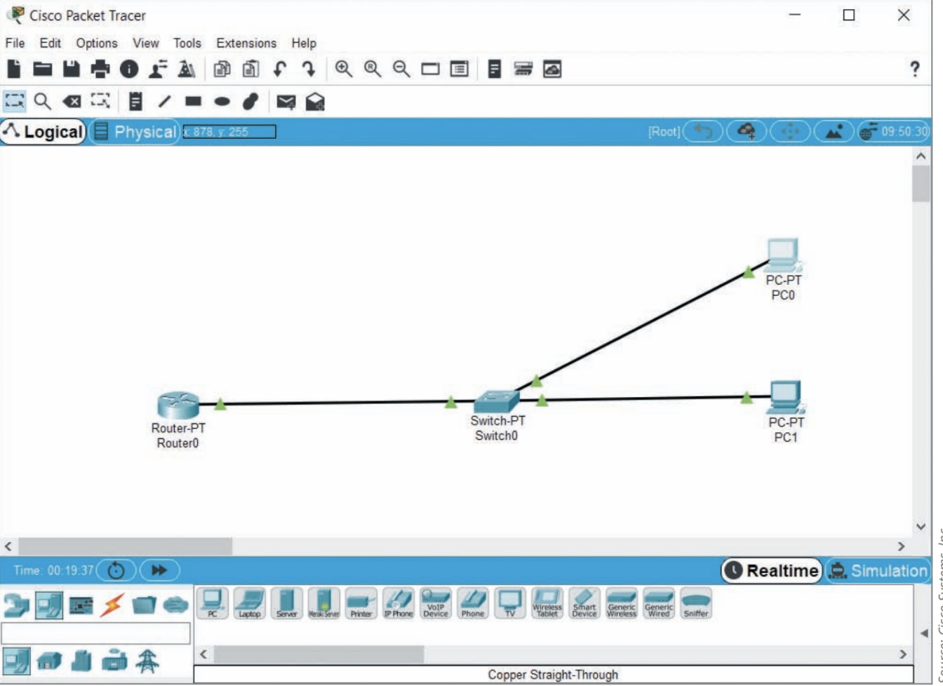
3. Use Copper straight-Through cables to connect the PCs to the switch and the switch to the router using the interfaces configured above (see Figure 8-31). Wait for all connections to show green triangles on both ends.

4. Ping the following connections to determine whether they work:
a. From PC0, ping the router. What command did you use? Did it work? Why or why not?
b. From PC0, ping PC1. What command did you use? Did it work? Why or why not?
c. From Router0, ping PC0. What command did you use? Did it work? Why or why not?
d. From Router0, ping PC1. What command did you use? Did it work? Why or why not?
As you can see, only devices within the routers own subnet can communicate with the router. However, can devices on a different subnet from the router but connected to the same switch communicate with each other? To find out, complete the following steps:
5. Add a new pC to the workspace and configure it with the following information:
a. PC2s FastEthernet0 interface:
IP Address: 192.168.3.150
Subnet Mask: 255.255.255.0
Default Gateway: 192.168.2.1 6.
6. Use a Copper straight-Through cable to connect PC2 to the switch. Wait for the connection to show green triangles on both ends.
7. Ping the following connections to determine whether they work:
a. From PC2, ping PC0. What command did you use? Did it work? Why or why not?
b. From PC2, ping PC1. What command did you use? Did it work? Why or why not?
c. From PC2, ping the router. What command did you use? Did it work? Why or why not?
Based on these results, you can see that a switch might successfully send messages between devices within various subnets if those messages can rely on broadcasts (such as ping). However, all devices on a routers interface must be configured to use the same subnet as the router in order to reach that router and send messages outside the LAN. What happens when you daisy-chain multiple switches on a single router interface? To find out, complete the following steps:
8. Delete the connection between PC2 and Switch0 (but do not delete the PC or the switch).
9. Add a new pT-switch to the workspace. Use a Copper Cross-over cable to connect the two switches. Use a Copper straight-Through cable to connect PC2 to Switch1. Wait for the connections to show green triangles on both ends.
10. Ping the following connections to determine whether they work:
a. From PC0, ping PC2. What command did you use? Did it work? Why or why not?
b. From PC1, ping PC2. What command did you use? Did it work? Why or why not?
Even with multiple switches, the same limitations apply: Only devices within the same subnet can communicate with each other. What happens if you move one switch to a different router interface? Will devices on the same subnet across both switches continue to be able to communicate with each other? To find out, complete the following steps:
11. Delete the connection between the two switches. Configure the router with the following information:
a. Router0s FastEthernet1/0 interface:
IP Address: 192.168.3.1
Subnet Mask: 255.255.255.0
Port Status: on
12. Use a Copper straight-Through cable to connect Switch1 to the routers FastEthernet1/0 interface. Wait for the connections to show green triangles on both ends.
13. On the routers CLI tab, enter the exit command twice and then enter the command show ip route. Which two networks is the router aware of ?
14. Ping the following connections to determine whether they work:
a. From PC2, ping the routers FastEthernet1/0 interface. What command did you use? Did it work? Why or why not?
b. From PC2, ping PC0. What command did you use? Did it work? Why or why not?
c. From PC2, ping PC1. What command did you use? Did it work? Why or why not?
15. Add a new pC to the workspace and configure it with the following information: a. PC3s FastEthernet0 interface:
IP Address: 192.168.3.200
Subnet Mask: 255.255.255.0
Default Gateway: 192.168.2.1
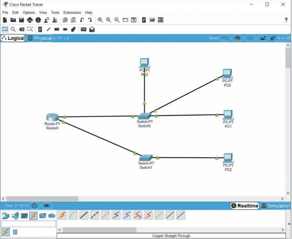
16. Use a Copper straight-Through cable to connect PC3 to Switch0 (see Figure 8-32). Wait for the connection to show green triangles on both ends before continuing with the next step

17. In the lower right corner, click simulation.
18. From PC1, ping PC3. In the Simulation Panel, click the play (Alt 1 p) button. After the first message passes through the switch, click the play (Alt 1 p) button again to pause the simulation. What did the switch do with the ping request? Continue the ping simulation to see that PC3 is able to respond to the ping because subnets alone do not limit broadcast domains.
19. Take a screenshot of your Packet Tracer network; submit this visual with your answers to this projects questions. You can save your project for future reference and experimentation; however, you will not need this network file for future projects in this course.
Cisco Packet Tracer File Edit Options View Tools Extensions Help . Logical Physical 878255 Cisco Packet Tracer LogicalStep by Step Solution
There are 3 Steps involved in it
Step: 1

Get Instant Access to Expert-Tailored Solutions
See step-by-step solutions with expert insights and AI powered tools for academic success
Step: 2

Step: 3

Ace Your Homework with AI
Get the answers you need in no time with our AI-driven, step-by-step assistance
Get Started


