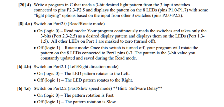
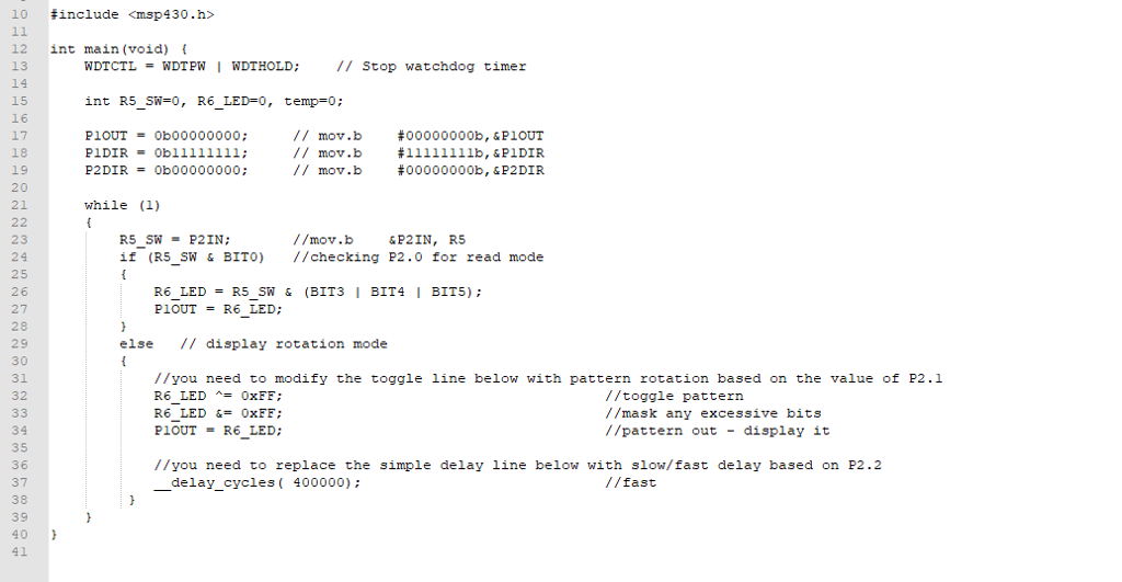
Please read this carefully. A skeleton was provided. Program must be in C.


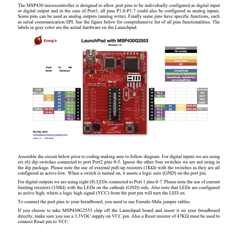
The MSP430 microcontroller is designed to allow port pins to be individually configured as digital input or digital output and in the case of Port, all pins P1.0-P1.7 could also be configured as analog inputs. Some pins can be used as analog outputs (analog write). Finally some pins have specific functions, such as serial communication SPI. See the figure below for comprehensive list of all pins functionalities. The labels in gray color are the actual hardware on the Launchpad. LaunchPad with MSP430G2553 Revision 1.5 Energia Flash Serial 16 KB J3 Jumpers : EMULATION- MSP-EXP43062 P1.0 2P1. e P1.1 4 P1.2 A3 P1-3 D1.3 O P1.4 19 P26 18 I P2.7 17 16 A0 P1.1 3 XOUT TEST A2 P1 2 RST P1.4 6 P1.57 MOSI (B0 MISO (B0 REEN O14 P1.6 P2.1 9P2.1 P2 2 10 P2.1 OO 28pin P2.3 12 P2 4 11 P2 3 TEXAS Rei Vilo, 2012 LounchPad Assemble the circuit below prior to coding making sure to follow diagram. For digital inputs we are using six (6) dip switches connected to port Port2 pins 0-5. Ignore the other four switches we are not using in the dip package. Please note the use of external pull-up resisters (1 K(2) with the switches as they are all configured as active-low. When a switch is turned on, it assets a logic zero (GND) on the port pin. For digital outputs we are using eight (8) LEDs connected to Port 1 pins 0-7. Please note the use of current limiting resistors (3302) with the LEDs on the cathode (GND) side. Also note that LEDs are configured as active high, where a logic high signal (VCC) from the port pin will turn the LED on. To connect the port pins to your breadboard, you need to use Female-Male jumper cables. If you choose to take MSP430G2553 chip off the Launchpad board and insert it on your breadboard directly, make sure you use a 3.3VDC supply on VCC pin. Also a Reset resistor of 47KQ must be used to connect Reset pin to VCC. The MSP430 microcontroller is designed to allow port pins to be individually configured as digital input or digital output and in the case of Port, all pins P1.0-P1.7 could also be configured as analog inputs. Some pins can be used as analog outputs (analog write). Finally some pins have specific functions, such as serial communication SPI. See the figure below for comprehensive list of all pins functionalities. The labels in gray color are the actual hardware on the Launchpad. LaunchPad with MSP430G2553 Revision 1.5 Energia Flash Serial 16 KB J3 Jumpers : EMULATION- MSP-EXP43062 P1.0 2P1. e P1.1 4 P1.2 A3 P1-3 D1.3 O P1.4 19 P26 18 I P2.7 17 16 A0 P1.1 3 XOUT TEST A2 P1 2 RST P1.4 6 P1.57 MOSI (B0 MISO (B0 REEN O14 P1.6 P2.1 9P2.1 P2 2 10 P2.1 OO 28pin P2.3 12 P2 4 11 P2 3 TEXAS Rei Vilo, 2012 LounchPad Assemble the circuit below prior to coding making sure to follow diagram. For digital inputs we are using six (6) dip switches connected to port Port2 pins 0-5. Ignore the other four switches we are not using in the dip package. Please note the use of external pull-up resisters (1 K(2) with the switches as they are all configured as active-low. When a switch is turned on, it assets a logic zero (GND) on the port pin. For digital outputs we are using eight (8) LEDs connected to Port 1 pins 0-7. Please note the use of current limiting resistors (3302) with the LEDs on the cathode (GND) side. Also note that LEDs are configured as active high, where a logic high signal (VCC) from the port pin will turn the LED on. To connect the port pins to your breadboard, you need to use Female-Male jumper cables. If you choose to take MSP430G2553 chip off the Launchpad board and insert it on your breadboard directly, make sure you use a 3.3VDC supply on VCC pin. Also a Reset resistor of 47KQ must be used to connect Reset pin to VCC


