

Answered step by step
Verified Expert Solution
Question
1 Approved Answer
Please write a working code for Milestone 3 in visual studio asap. All the information is already attached 2.1 Milestone 1: Logic gates library -
Please write a working code for Milestone 3 in visual studio asap.
All the information is already attached
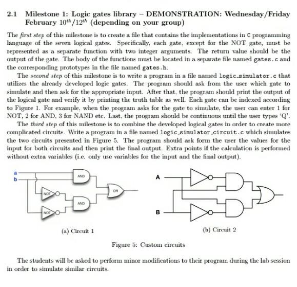
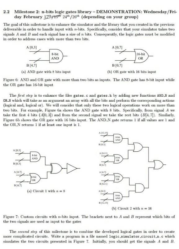
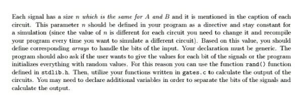
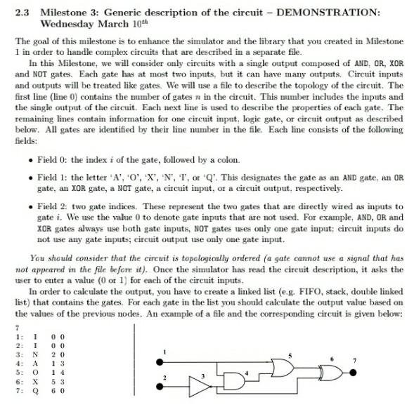
2.1 Milestone 1: Logic gates library - DEMONSTRATION: Wednesday/Friday February 10/12th (depending on your group) The first step of this milestone is to create a file that contains the implementations in C programming language of the seven logical gates. Specifically, each gate, except for the NOT gate, must be represented as a separate function with two integer arguments. The return value should be the output of the gate. The body of the functions must be located in a separate file named gates.c and the corresponding prototypes in the file namned gates.h. The second step of this milestone is to write a program in a file named logic.simulator.c that utilizes the already developed logic gates. The program should ask from the user which gate to simulate and then ask for the appropriate input. After that, the program should print the output of the logical gate and verify it by printing the truth table as well. Each gate can be indexed according to Figure 1. For example, when the program asks for the gate to similate, the user can enter 1 for NOT, 2 for AND, 3 for NAND etc. Last, the program should be continuous until the user types Q'. The third step of this milestone is to combine the developed logical gates in order to create more complicated circuits. Write a program in a file named logic simulator circuit.c which simulates the two circuits presented in Figure 5. The program should ask form the user the values for the input for both circuits and then print the final output. Extra points if the calculation is performed without extra variables (i.e. only use variables for the input and the final output). AND AND NOT B (a) Circuit 1 (b) Circuit 2 Figure 5: Custoin circuits The students will be asked to perform minor modifications to their program during the lab session in order to simulate similar circuits. 16-bit OR 2.2 Milestone 2: n-bits logic gates library - DEMONSTRATION: Wednesday/Fri- day February 17441gff 24" /26 (depending on your group) The goal of this milestone is to enhance the simulator and the library that you created in the previous deliverable in order to handle input with no- bits. Specifically, consider that your simulator takes two signals A and B and each signal has a size of n bits. Consequently, the logic gates must be modified in order to address cases with more than two bits. A [0.3) A [071 8-bit AND B[4.7) B[0,7) (a) AND gate with 8 bits input (b) OR gate with 16 bits input Figure 6: AND and OR gate with more than two bits as inputs. The AND gate has 8-bit input while the OR gate has 16-bit input The first step is to enhance the files gates.c and gates.h by adding new functions AND_N and ORN which will take as an argument an array with all the bits and perform the corresponding actions (logical and, logical or). We will consider that only these two logical operations work on more than two bits. For example, Figure 6a shows the AND gate with 8 bits. Specifically, from signal A we take the first 4 bits (4(0,3]) and from the second signal we take the rest bits (B(4.7]). Similarly, Figure 6b shows the OR gate with 16 bits input. The AND N gate returns 1 if all values are 1 and the OR_N returns 1 if at least one input is 1. A [19.15) AND [0.31 A[03] AKO R-hi AND 8.b OR B[0,31 94.71 A 14.71 A 14.71 x-bit CR OR B 14.73 BILI (a) Circuit 1 with = 8 A031 -bil AND [12.15 (b) Circuit 2 with n = 16 Figure 7: Custom circuits with n-bits input. The brackets next to A and B represent which bits of the two signals are used as input to the gates The second step of this milestone is to combine the developed logical gates in order to create more complicated circuits. Write a program in a file named logic.simulator.circuit.n.c which simulates the two circuits presented in Figure 7. Initially, you should get the signals A and B. Each signal has a size n which is the same for A and B and it is mentioned in the caption of each circuit. This parameter n should be defined in your program as a directive and stay constant for a simulation (since the value of n is different for each circuit you need to change it and recompile your program every time you want to simulate a different circuit). Based on this value, you should defime corresponding arrays to handle the bits of the input. Your declaration must be generic. The program should ako ask if the user wants to give the values for each bit of the signals or the initializes everything with random values. For this reason you can use the function rand() function defined in stdlib.h. Then, titilize your functions written in gates.c to calculate the output of the circuits. You may need to declare additional variables in order to separate the bits of the signals and calculate the output. program 2.3 Milestone 3: Generic description of the circuit - DEMONSTRATION: Wednesday March 10th The goal of this milestone is to enhance the simulator and the library that you created in Milestone 1 in order to handle complex circuits that are described in a separate file. In this Milestone, we will consider only circuits with a single output composed of AND, OR, XOR and NOT gates. Each gate has at most two inputs, but it can have many outputs. Circuit inputs and outputs will be treated like gates. We will use a file to describe the topology of the circuit. The first line (line 0) contains the mumber of gates n in the circuit. This mumber includes the inputs and the single output of the circuit. Each next line is used to describe the properties of each gate. The remaining lines contain information for one circuit input, logic gate, or circuit output as described below. All gates are identified by their line mimber in the file. Each line consists of the following fields: Field 0: the index i of the gate, followed by a colon. Field 1: the letter 'A', '0', 'X', 'N', 'T', or 'Q'. This designates the gate as an AND gate. an OR gate, an XOR gate, a NOT gate, a circuit input, or a circuit output, respectively. Field 2: two gate indices. These represent the two gates that are directly wired as inputs to gate i. We use the value 0 to denote gate inputs that are not used. For example, AND, OR and XOR gates always use both gate inputs, NOT gates use only one gate input; circuit inputs do not use any gate inputs; circuit output use only one gate input. You should consider that the circuit is topologically ordered (a gate cannot use a signal that has not appeared in the file before it). Once the simulator has read the circuit description, it asks the user to enter a value (0 or 1) for each of the circuit inputs. In order to calculate the output, you have to create a linked list (e.g. FIFO, stack, double linked list) that contains the gates. For each gate in the list you should calculate the output value based on the values of the previous nodes. An example of a file and the corresponding circuit is given below: 7 1: 2: 00 00 20 4: 1 1 N A 0 Q 14 5 3 60 6: 7: eberStep by Step Solution
There are 3 Steps involved in it
Step: 1

Get Instant Access to Expert-Tailored Solutions
See step-by-step solutions with expert insights and AI powered tools for academic success
Step: 2

Step: 3
Ace Your Homework with AI
Get the answers you need in no time with our AI-driven, step-by-step assistance
Get Started
From Herds To Insights Harnessing Data Analytics For Sustainable Livestock Farming
Authors: Prof Suresh Neethirajan
1st Edition
B0CFD6K6KK, 979-8857075487