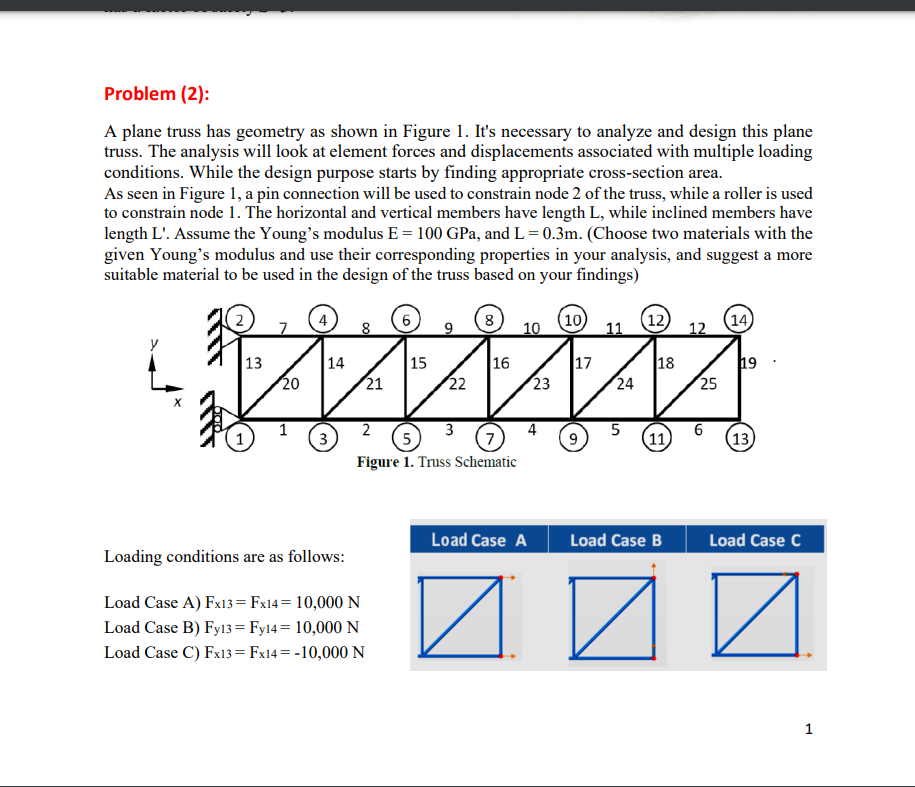
Problem (2): A plane truss has geometry as shown in Figure 1. It's necessary to analyze and design this plane truss. The analysis will look at element forces and displacements associated with multiple loading conditions. While the design purpose starts by finding appropriate cross-section area. As seen in Figure 1, a pin connection will be used to constrain node 2 of the truss, while a roller is used to constrain node 1. The horizontal and vertical members have length L, while inclined members have length L'. Assume the Young's modulus E = 100 GPa, and L = 0.3m. (Choose two materials with the given Young's modulus and use their corresponding properties in your analysis, and suggest a more suitable material to be used in the design of the truss based on your findings) 2 4 6 8 (10) (12) 14) 7 8 10 11 12 13 14 15 16 17 18 19 ZZZZZZ 20 21 22 23 24 25 1 2 3 5 6 3 5 7 9 (11) 13 Figure 1. Truss Schematic Load Case A Load Case B Load Case C Loading conditions are as follows: Load Case A) Fx13= Fx14=10,000 N Load Case B) Fy13= Fy14 = 10,000 N Load Case C) Fx13= Fx14 = -10,000 N 1 Problem (2): A plane truss has geometry as shown in Figure 1. It's necessary to analyze and design this plane truss. The analysis will look at element forces and displacements associated with multiple loading conditions. While the design purpose starts by finding appropriate cross-section area. As seen in Figure 1, a pin connection will be used to constrain node 2 of the truss, while a roller is used to constrain node 1. The horizontal and vertical members have length L, while inclined members have length L'. Assume the Young's modulus E = 100 GPa, and L = 0.3m. (Choose two materials with the given Young's modulus and use their corresponding properties in your analysis, and suggest a more suitable material to be used in the design of the truss based on your findings) 2 4 6 8 (10) (12) 14) 7 8 10 11 12 13 14 15 16 17 18 19 ZZZZZZ 20 21 22 23 24 25 1 2 3 5 6 3 5 7 9 (11) 13 Figure 1. Truss Schematic Load Case A Load Case B Load Case C Loading conditions are as follows: Load Case A) Fx13= Fx14=10,000 N Load Case B) Fy13= Fy14 = 10,000 N Load Case C) Fx13= Fx14 = -10,000 N 1


