

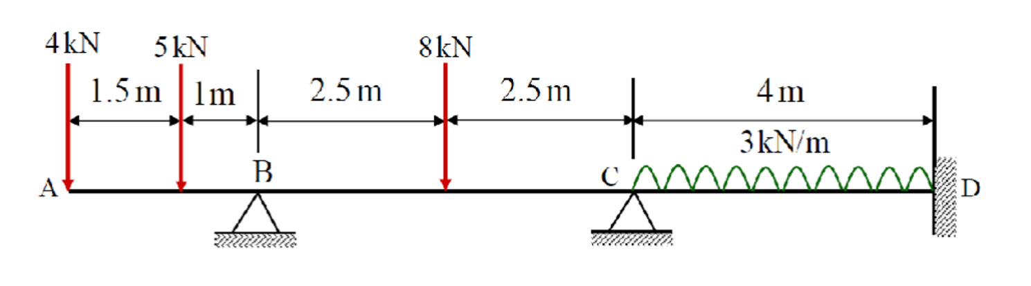
Question: Q . 1 : Taking nodes at A , B , C , and D of the beam shown below, identify the nodal displacementsQ .
Q: Taking nodes at A B C and D of the beam shown below, identify the nodal displacementsQ: Taking nodes at A B C and D of the beam shown below, identify the nodal displacements
DOF of the structure and write the nodal displacement vector in terms of these DOF.
Calculate the nodal load vector and the stiffness matrix for the beam.
Solve the governing equation to calculate the nodal displacement vector
Using the values of determine the member end forces and moments, and combine those with
the corresponding contributions due to fixed end conditions.
Utilise these values, draw the shear force SF and bending moment BM diagrams of the beam.
Show the values of SF and BM at important sections member end sections, sections subjected
point loads, maximum moment with a member subjected to distributed load Also show the sign
conventions you used for the SF and BM
The beam has uniform flexural rigidity where GPa and
Note: the placement of the load on is unsymmetrical calculate its fixed end forces
carefully using moment equilibrium equation taking its free body diagram
As the force is acting directly at node nodal load and not inside the member not
member load it will not contribute any fixed end moment thus, it need not be considered
unnecessarily in the calculations of fixed end forces and moments. However, it must be considered
finally in the calculation of where it will simply be added algebraically considering proper
directionsign as the nodal load.
DOF of the structure and write the nodal displacement vector X in terms of these DOF.
Calculate the nodal load vector P and the stiffness matrix K for the beam.
Solve the governing equation KXP to calculate the nodal displacement vector X
Using the values of X determine the member end forces and moments, and combine those with
the corresponding contributions due to fixed end conditions.
Utilise these values, draw the shear force SF and bending moment BM diagrams of the beam.
Show the values of SF and BM at important sections member end sections, sections subjected
point loads, maximum moment with a member subjected to distributed load Also show the sign
conventions you used for the SF and BM
The beam has uniform flexural rigidity EI where E GPa and I x mm
Step by Step Solution
There are 3 Steps involved in it
1 Expert Approved Answer
Step: 1 Unlock

Question Has Been Solved by an Expert!
Get step-by-step solutions from verified subject matter experts
Step: 2 Unlock
Step: 3 Unlock