

Question: Lab 3: Kirchhoff's Voltage and Current Laws Objective The objective of this Lab activity is to verify Kirchhoff's Voltage Law (KVL) and Kirchhoff's Current
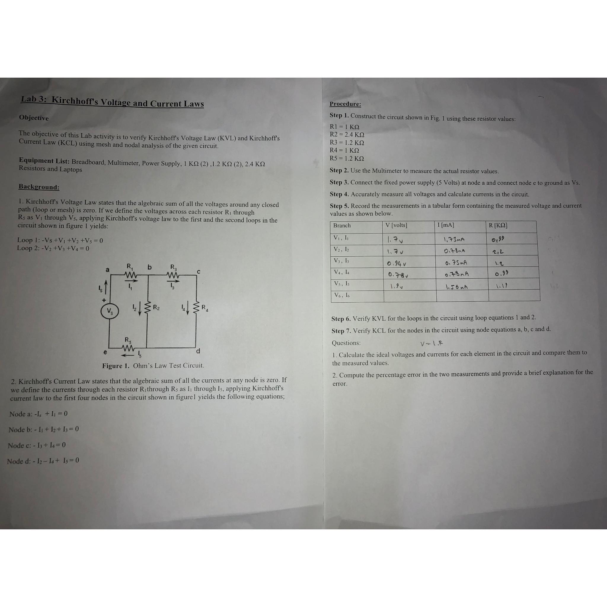
Lab 3: Kirchhoff's Voltage and Current Laws Objective The objective of this Lab activity is to verify Kirchhoff's Voltage Law (KVL) and Kirchhoff's Current Law (KCL) using mesh and nodal analysis of the given circuit. Equipment List: Breadboard, Multimeter, Power Supply, 1 KS (2),1.2 KQ (2), 2.4 K Resistors and Laptops Background: 1. Kirchhoff's Voltage Law states that the algebraic sum of all the voltages around any closed path (loop or mesh) is zero. If we define the voltages across each resistor R through Rs as V through Vs, applying Kirchhoff's voltage law to the first and the second loops in the circuit shown in figure 1 yields: Loop 1: -Vs +V +V +V5 = 0 Loop 2: -V +V3 +V4 = 0 a + R e b R R LR d Figure 1. Ohm's Law Test Circuit. 2. rchhoff's Current Law states that the algebraic sum of all the currents at any node is zero. If we define the currents through each resistor R through Rs as I through Is, applying Kirchhoff's current law to the first four nodes in the circuit shown in figurel yields the following equations; Node a: -Is + = 0 Node b: 1+12+13= 0 Node c: - 13 + 14 = 0 Node d: - 12-14+ 15 = 0 Procedure: Step 1. Construct the circuit shown in Fig. 1 using these resistor values: R1 = 1 KQ R2 = 2.4 KQ R3 = 1.2 R4 = 1 R5 = 1.2 KQ Step 2. Use the Multimeter to measure the actual resistor values. Step 3. Connect the fixed power supply (5 Volts) at node a and connect node e to ground as Vs. Step 4. Accurately measure all voltages and calculate currents in the circuit. Step 5. Record the measurements in a tabular form containing the measured voltage and current values as shown below. V [volts] Branch V, I V2, I2 V3, 13 V4, I4 Vs, Is V6, 16 1.70 1,70 0.94 v 0.781 I [mA] 1,73MA 078nA 0.75mA 0.78mA 1.56 MA R [] 0,99 2,2 1.2 0.99 Step 6. Verify KVL for the loops in the circuit using loop equations 1 and 2. Step 7. Verify KCL for the nodes in the circuit using node equations a, b, c and d. Questions: V - 1.R 1. Calculate the ideal voltages and currents for each element in the circuit and compare them to the measured values. 2. Compute the percentage error in the two measurements and provide a brief explanation for the error.
Step by Step Solution
3.44 Rating (160 Votes )
There are 3 Steps involved in it

Get step-by-step solutions from verified subject matter experts