Answered step by step
Verified Expert Solution
Question
1 Approved Answer
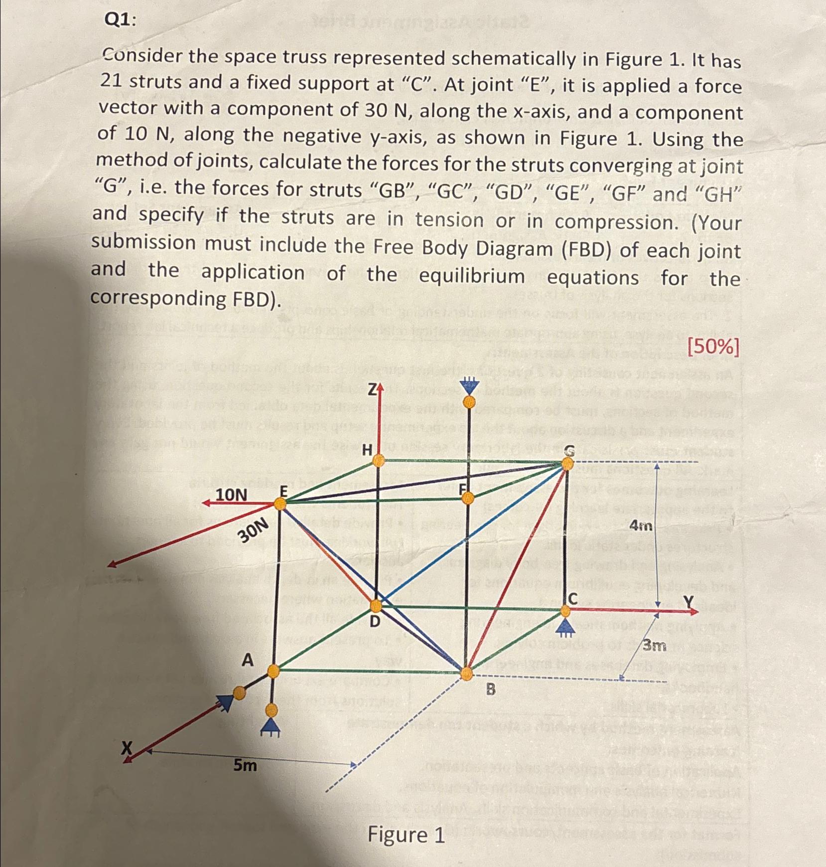
Q1: Consider the space truss represented schematically in Figure 1. It has 21 struts and a fixed support at C. At joint E, it

Q1: Consider the space truss represented schematically in Figure 1. It has 21 struts and a fixed support at "C". At joint "E", it is applied a force vector with a component of 30 N, along the x-axis, and a component of 10 N, along the negative y-axis, as shown in Figure 1. Using the method of joints, calculate the forces for the struts converging at joint "G", i.e. the forces for struts "GB", "GC", "GD", "GE", "GF" and "GH" and specify if the struts are in tension or in compression. (Your submission must include the Free Body Diagram (FBD) of each joint and the application of the equilibrium equations for the corresponding FBD). 10N E 30N H A D 5m ZA Figure 1 B G 4m C 3m [50%]
Step by Step Solution
There are 3 Steps involved in it
Step: 1

Get Instant Access to Expert-Tailored Solutions
See step-by-step solutions with expert insights and AI powered tools for academic success
Step: 2

Step: 3

Ace Your Homework with AI
Get the answers you need in no time with our AI-driven, step-by-step assistance
Get Started


