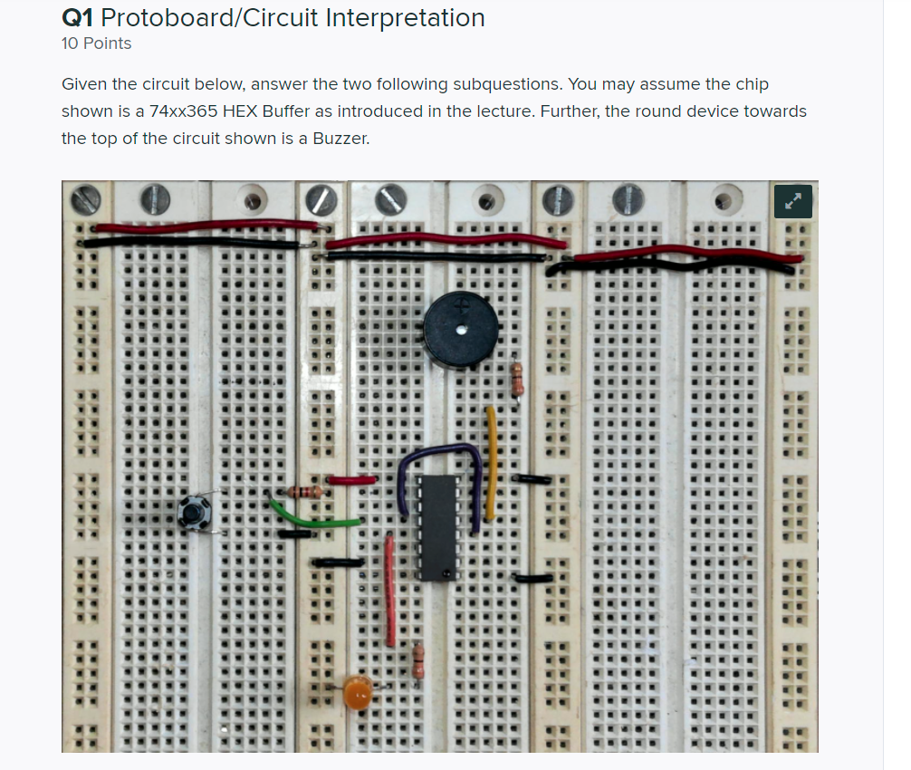


Q1 Protoboard/Circuit Interpretation 10 Points Given the circuit below, answer the two following subquestions. You may assume the chip shown is a 74xx365 HEX Buffer as introduced in the lecture. Further, the round device towards the top of the circuit shown is a Buzzer. RA Q1.1 3 Points There are THREE wiring issues with the shown circuit (e.g., missing wires or incorrectly placed wires). Give a concise description of each error below. You may want to do Q1.2 first if these errors are hard to find. Error 1: Enter your answer here Error 2: Enter your answer here Error 3: Enter your answer here Q1.2 7 Points Draw the schematic for the circuit with the errors listed above corrected. You may assume the the power supply is +5V and GND. In drawing the 74xx365 buffer chip, please draw a full chip symbol. It does not need to match the symbol as shown in the lecture (namely, it just needs all the pins labeled and connected correctly - where ever those pins are shown). For the buzzer, you may use a circle with two lines coming from it as a symbol, with a + sign marking the positive pin. You do not need to fill in resistor values. You may draw the circuit however you wish - pen and paper, Fritzing, MS Paint, pSpice, etc... Upload as a picture or PDF. Q1 Protoboard/Circuit Interpretation 10 Points Given the circuit below, answer the two following subquestions. You may assume the chip shown is a 74xx365 HEX Buffer as introduced in the lecture. Further, the round device towards the top of the circuit shown is a Buzzer. RA Q1.1 3 Points There are THREE wiring issues with the shown circuit (e.g., missing wires or incorrectly placed wires). Give a concise description of each error below. You may want to do Q1.2 first if these errors are hard to find. Error 1: Enter your answer here Error 2: Enter your answer here Error 3: Enter your answer here Q1.2 7 Points Draw the schematic for the circuit with the errors listed above corrected. You may assume the the power supply is +5V and GND. In drawing the 74xx365 buffer chip, please draw a full chip symbol. It does not need to match the symbol as shown in the lecture (namely, it just needs all the pins labeled and connected correctly - where ever those pins are shown). For the buzzer, you may use a circle with two lines coming from it as a symbol, with a + sign marking the positive pin. You do not need to fill in resistor values. You may draw the circuit however you wish - pen and paper, Fritzing, MS Paint, pSpice, etc... Upload as a picture or PDF


