Answered step by step
Verified Expert Solution
Question
1 Approved Answer
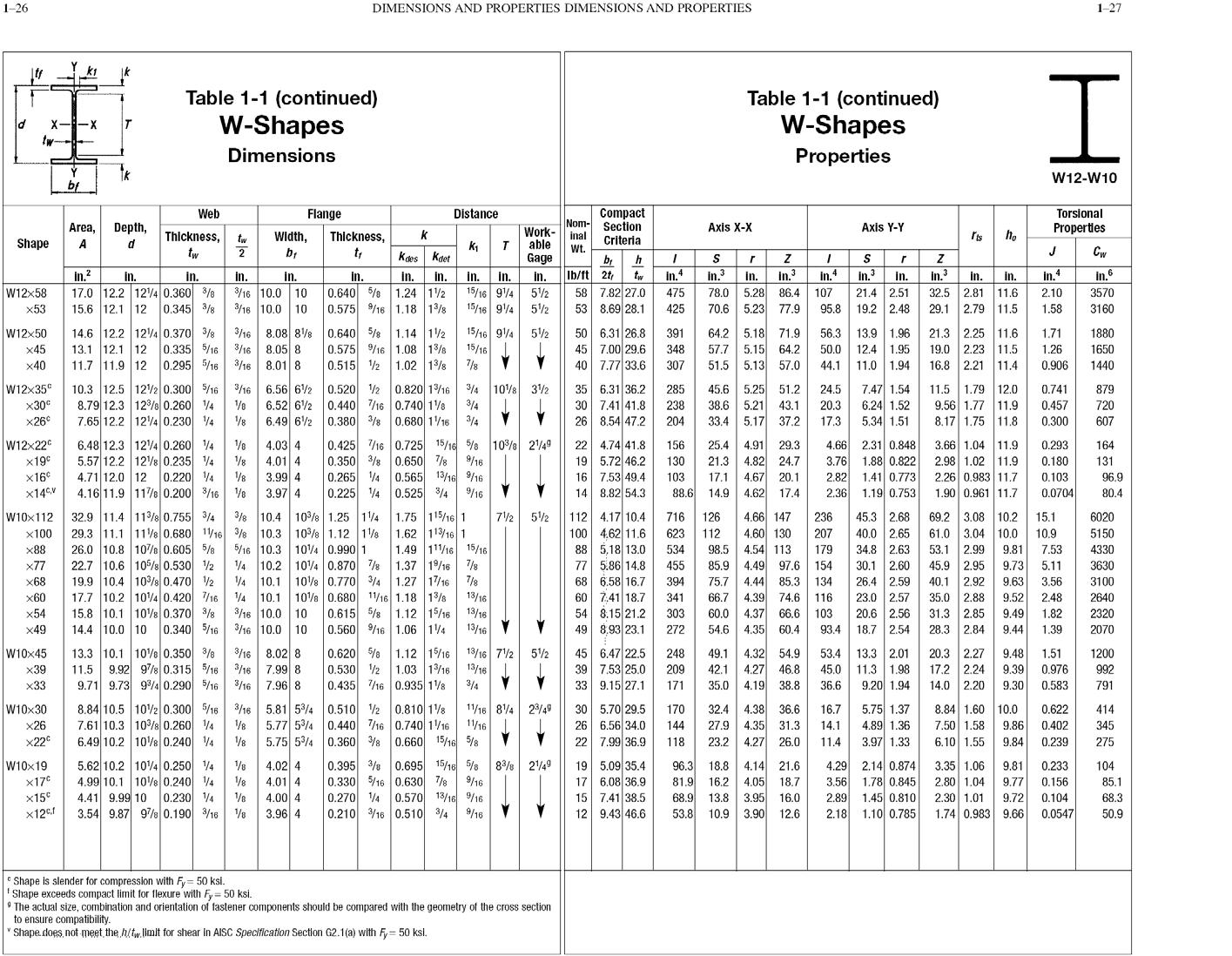
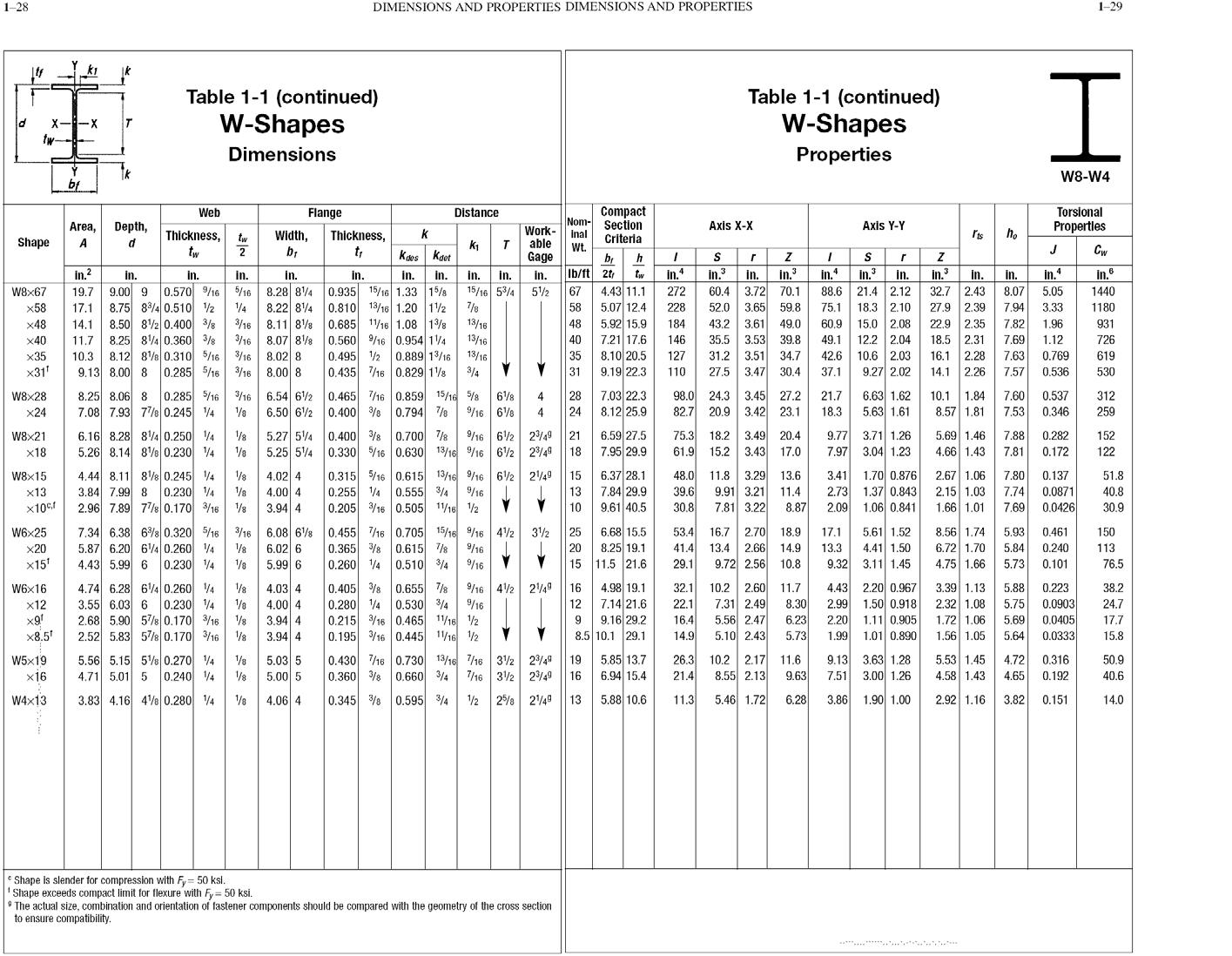
Select a steel Beam using the W section from the AISC Manual for flexural members to support a service dead load of 1.0 k/ft (not
Select a steel Beam using the “W” section from the AISC Manual for flexural members to support a service dead load of 1.0 k/ft (not including beam self-weight) & service lives load of 1.6 k/ft over the simply supported span of 18 ft. The beam section is made of A992 steel (fy=50 ksi). Also, calculate un-braced length “LP”.


1-26 DIMENSIONS AND PROPERTIES DIMENSIONS AND PROPERTIES 1-27 Table 1-1 (continued) W-Shapes Table 1-1 (continued) W-Shapes I. X--X tw Dimensions Properties W12-W10 b Compact Section Web Flange Distance Torsional Nom- Work- inal able Area, Depth, Axis X-X Axis Y-Y Properties k ho Thickness, tw Width, Thickness, t; Shape A d tw Criteria k Koes Kdet Wt. b Ib/ft 2t 58 7.82 27.0 53 8.69 28.1 Cw Gage h in.4 in.3 in. 5.28 70.6 5.23 77.9 in.4 in3 in.3 in. in. in.6 in.? 17.0 12.2 124 0.360 /8 15.6 12.1 12 in. in. 32.5 2.81 11.6 29.1 2.79 11.5 in. in. in. in. in. in. in. in. in. in. In. 0.640 5/% 1.24 12 0.575 9/16 1.18 1/8 15/16 94 15/16 94 21.4 2,51 19.2 2.48 W12x58 3/16 10.0 10 3/16 10.0 10 52 52 475 78.0 86.4 107 2.10 3570 x53 0.345 3/8 425 95.8 1.58 3160 15/16 94 14.6 12.2 124 0.370 3/8 13.1 12.1 12 1.14 12 0.575 %16 1.08 13/8 1.02 13/8 64.2 5.18 71.9 57.7 5.15 64.2 51.5 5.13 0.640 5/8 50 6.31 26.8 45 7.00 29.6 40 7.77 33.6 13.9 1,96 12.4 1.95 11.0 1.94 21.3 2.25 11,6 19.0 2.23 11,5 16.8 2.21 11.4 W12x50 8.08 8% 3/16 3/16| 8.05 8 0.295 5/16 3/16 8.01 8 391 56.3 1.71 1880 x45 0.335 5/16 15/16 348 50.0 1.26 1650 x40 11.7 11.9 12 0.515 2 7/8 307 57.0 44.1 0.906 1440 W12x35 x30 10.3 12.5 12/2 0.300 5/16 8.79 12.3 12%8 0.260 4 7.65 12.2 124 0.230 4 0.520 2 0.440 7/16 0.740 18 6.49 62 0,380 3/8 0.680 116 34 6.56 62 6.52 62 0.820 1%16 4 108 32 3/4 35 6.31 36.2 30 7.41 41.8 26 8.54 47.2 45,6 5.25 38.6 5.21 43.1 33.4 5.17 37.2 7.47 1.54 6.24 1.52 5.34 1,51 11.5 1.79 12.0 9.56 1.77 11.9 8.17 1.75 11.8 3/16 285 51.2 24.5 0.741 879 238 20.3 0.457 720 x26 204 17.3 0,300 607 0.425 /16 0.725 15/16 5/8 10% 249 0.350 3/8 0.650 7/8 0.265 4 0.225 4 0.525 34 9/16 25.4 4.91 29.3 4.82 24.7 4.67 20.1 4.62 4.66 2.31 0.848 3.76 1.88 0.822 1.41 0.773 1.19 0.753 W12x22 6.48 12.3 124 0.260 4 5.57 12.2 128 0.235 4 4.71 12.0 12 0.220 4 4.16 11.9 11/e 0.200 3/16 V8 4.03 4 1/8 22 4.74 41.8 19 5.72 46.2 16 7.53 49.4 14 8.82 54.3 3.66 1.04 11.9 2.98 1.02 11.9 2.26 0.983 11.7 1.90 0.961 11.7 156 0.293 164 4.01 4 3.99 4 3.97 4 x19 9/16 130 21.3 0.180 131 x16 0.565 13/16 %h6 103 17.1 2.82 0.103 96.9 x14cv 88.6 14.9 17.4 2.36 0.0704 80.4 3/8 10,4 103/8 1,25 14 32.9 11.4 11%8 0.755 34 29.3 11.1 118 0.680 1V16 38 10.3 10%8 1.12 18 26.0 10.8 1078 0.605 5/8 22.7 10.6 105/s 0.530 2 19.9 10.4 10/8 0.470 2 17.7 10.2 104 0.420 16 15.8 10.1 108 0.370 3/8 14.4 10.0 10 0.340 5/16 3/16 10.0 10 1.75 115/16 1 1.62 113/16 1 1.49 111/16 15/16 1.37 1/16 /8 1.27 17/16 7/8 112 4.17 10.4 100 4,62 11.6 88 5,18 13.0 77 5.86 14.8 68 6.58 16.7 60 7,41 18.7 54 8.15 21.2 49 8.93 23.1 4.66 147 4.60 130 98.5 4.54 113 85.9 4.49 97.6 75.7 4.44 85.3 4.39 4.37 54.6 4.35 60.4 45.3 2.68 40.0 2.65 34.8 2.63 30.1 2.60 26.4 2.59 23.0 2,57 20.6 2.56 18.7 2.54 69.2 3.08 10,2 61.0 3.04 10.0 53.1 2.99 45.9 2,95 40.1 2.92 35.0 2.88 31.3 2.85 28.3 2.84 W10x112 72 52 716 126 236 15.1 6020 x100 623 112 207 10.9 5150 x88 5/16 10.3 104 0.990 1 534 179 9.81 7.53 4330 104 0.870 7/s 108 0.770 3/4 10.2 4 10.1 14 10.1 10V% 0.680 1/16 1.18 13/8 3/16 10,0 10 x77 14 455 154 9.73 5.11 3630 x68 394 134 9,63 3.56 3100 x60 13/16 341 66.7 74.6 116 9.52 2.48 2640 0.615 5/8 0.560 9/16 1.06 14 1.12 15/16 13/16 13/16 V x54 303 60.0 66.6 103 9.49 1.82 2320 x49 272 93.4 9.44 1.39 2070 13.3 10.1 10% 0.350 /8 9,92 97/8 0.315 5/16 3/16 7.99 8 9.71 9.73 94 0.290 5/16 3/16 7.96 8 3/16 8.02 8 0.620 /% 1.12 1/16 13/16 72 0.530 2 45 6.47 22.5 39 7.53 25.0 33 9.15 27.1 4.32 54.9 4.27 4.19 38.8 13.3 2.01 11.3 1.98 9.20 1.94 20.3 2.27 17.2 2.24 14.0 2.20 52 W10x45 x39 248 49.1 53.4 9.48 1.51 1200 11.5 1.03 116 13/16 209 42.1 46.8 45.0 9.39 0.976 992 33 0.435 /16 0.935 1/8 3/4 171 35.0 36.6 9.30 0.583 791 8.84 10.5 102 0.300 5/16 3/16 5.81 54 0.510 2 0.810 18 7.61 10.3 10%8 0.260 4 6.49 10.2 108 0.240 4 11/16 84 2/4 11/16 30 5.70 29.5 26 6.56 34.0 22 7.99 36.9 32.4 4.38 36.6 27.9 4.35 31.3 23.2 4.27 26.0 5.75 1.37 4.89 1.36 3.97 1.33 8.84 1.60 10.0 7.50 1.58 6.10 1.55 W10x30 170 16.7 0.622 414 5.77 54 0.440 /16 0.740 1V16 5.75 54 0.360 8 0.660 15/16 5/8 x26 144 14.1 9.86 0.402 345 x22 118 11.4 9.84 0.239 275 4.02 4 4.01 4 4.00 4 3.96 4 0.395 3 0.695 15/16 5/8 19 5.09 35.4 17 6.08 36.9 15 7.41 38.5 12 9.43 46.6 96.3 18.8 4.14 21.6 16.2 4.05 18.7 81.9 68.9 13.8 3.95 53.8 10.9 3.90 12.6 2.14 0,874 1.78 0,845 1.45 0.810 2.18 1.10 0.785 3.35 1.06 2.80 1.04 2.30 1.01 1.74 0.983 9.66 5.62 10.2 104 0.250 4 83/8 249 W10x19 x17 x15 x12cf 1/8 4.29 9.81 0.233 104 4.99 10.1 108 0.240 4 4.41 9.99 10 0.230 V4 3.54 9.87 97/8 0.190 /18 0.330 5/16 0.630 7/8 9/16 9.77 0.156 3.56 85.1 0.270 4 0.570 13/16 9/16 16.0 2.89 9.72 0.104 68.3 1/8 0.210 /16 0.510 34 9/16 0.0547 50.9 c Shape is slender for compression with Fy= 50 ksl. ' Shape exceeds compact limit for flexure with Fy= 50 ksi. The actual size, combination and orientation of fastener components should be compared with the geometry of the cross section to ensure compatibility. Shape does not meet the hitw.limit for shear In AISC Specification Section G2.1(a) with F= 50 ksl.
Step by Step Solution
★★★★★
3.50 Rating (147 Votes )
There are 3 Steps involved in it
Step: 1

Get Instant Access to Expert-Tailored Solutions
See step-by-step solutions with expert insights and AI powered tools for academic success
Step: 2

Step: 3

Ace Your Homework with AI
Get the answers you need in no time with our AI-driven, step-by-step assistance
Get Started


