Question: Question 1a Ris) C's) Gels) K; s(s+5)(8 +15) Figure 12.1 Figure 1a.1 shows the block diagram of the closed loop control of the linearized magnetic
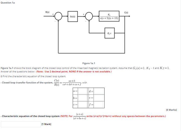
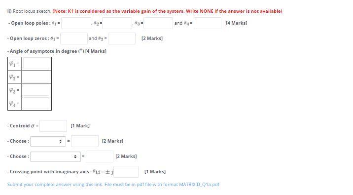
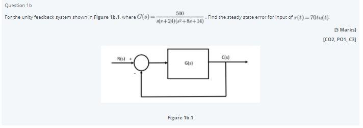
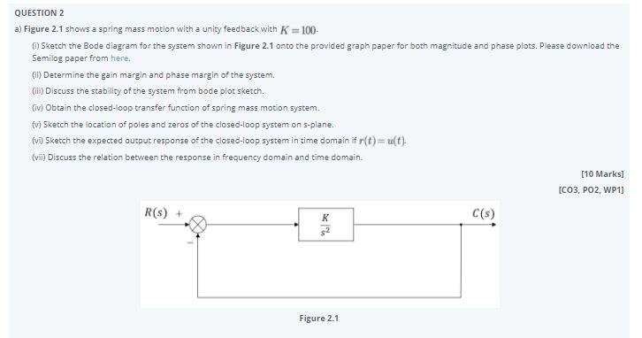
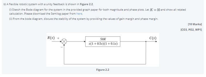
Question 1a Ris) C's) Gels) K; s(s+5)(8 +15) Figure 12.1 Figure 1a.1 shows the block diagram of the closed loop control of the linearized magnetic levitation system. Assume that Go (8)=1. K1=1 and Kj=1. Answer all the questions below : (Note: Use 2 decimal point, NONE if the answer is not available. i) Find the characteristic equation of the closed loop system. Cs) as + --- Closed loop transfer function of the system, with (8) col+d2+es+ d = b= [6 Marks] (8+) - Characteristic equation of the closed loop system (NOTE: For -write (s+a)/(s^2+bs+c) without any spaces between the parameters.) (2+b+c) [1 Mark] ii) Root locus sketch (Note: Kt is considered as the variable gain of the system. Write NONE if the answer is not available) - Open loop poles: 81 = 89 S3 = and 84 [4 Marks] - Open loop zeros: 81 = and 8 = [2 marks] - Angle of asymptote in degree [4 Marks) - Centroido [1 Mark] - Choose + [2 marks] - Choose [2 Marks] - Crossing point with imaginary axis : $12=; [1 Marks] Submit your complete answer using this link. File must be in pdf file with format MATRIXID_Q1a.pdf Question 1b 500 For the unity feedback system shown in Figure 16.1, where G(8) = of8+24)(2+88+14) Find the steady state error for input of r(t)=70tu(). [5 Marks) [CO2, P01, C3] Ris) CIS) G(s) Figure 16.1 QUESTION 2 a) Figure 2.1 shows a spring mass motion with a unity feedback with K=100 Sketch the Bode diagram for the system shown in Figure 2.1 onto the provided graph paper for both magnitude and phase plots. Please download the Semilog paper from here ) Determine the gain margin and phase margin of the system. (ii) Discuss the stability of the system from bode plot sketch. (iv) Obtain the closed-loop transfer function of spring mass motion system. {v} Sketch the location of poles and zeros of the closed-loop system on s-plane. (v Sketch the expected output response of the closed-loop system in time domain if r(t)=u(t) (vii) Discuss the relation between the response in frequency domain and time domain [10 Marks] [CO3, PO2, WP1) R(S) + C($) 52 K Figure 2.1 b) A flexible robotic system with a unity feedback is shown in Figure 2.2. ) Sketch the Bode diagram for the system in the provided graph paper for both magnitude and phase plots. Let K=10 and show all related calculation. Please download the Semilog paper from here. Ci) From the bode diagram, discuss the stability of the system by providing the values of gain margin and phase margin. [10 Marks] [CO3, PO2, WP1) R(S) + C($) SOK s(1 +0.58)(1 +0.18) Figure 2.2
Step by Step Solution
There are 3 Steps involved in it

Get step-by-step solutions from verified subject matter experts


