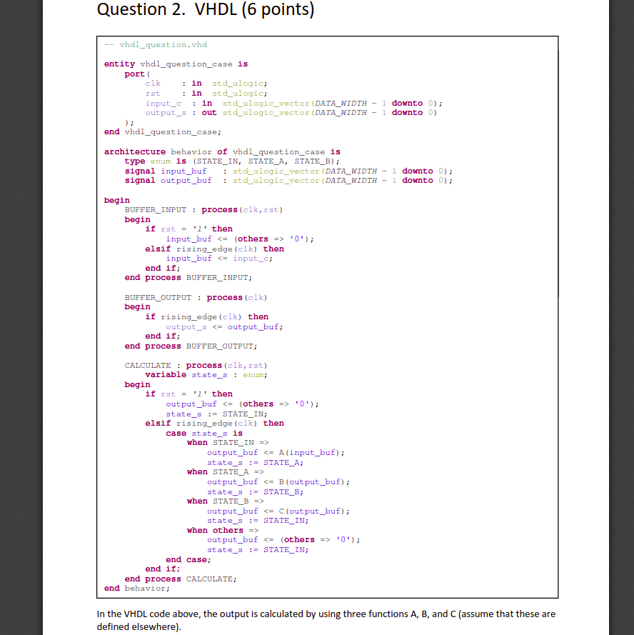

Question 2. VHDL (6 points) Ist vhdl_question.vhd entity vhdl_question_case is port clk : in std_ulogic; : in std_ulogic; input_c : in std_ulogic_vector (DATA_WIDTH - 1 downto 0); output_s : out std_ulogic_vector (DATA_WIDTH - 1 downto) end vhdl_question_case; architecture behavior of vhdl_question_case is type enum is (STATE_IN, STATE_A, STATE_B); signal input_buf : std_ulogic_vector (DATA_WIDTH - 1 downto 0); signal output_buf : std_ulogic_vector (DATA_WIDTH - 1 downto); begin BUFFER_INPUT : process (clk, rst) begin if rst = '1' then input_buf '0'); elsif rising_edge (clk) then input_buf '0'); state_s := STATE_IN; elsif rising_edge (clk) then case state_s is when STATE_IN => output_buf output_buf output_buf output_buf '0'); state_s := STATE_IN; end case; end if; end process CALCULATE; end behavior; In the VHDL code above, the output is calculated by using three functions A, B, and C (assume that these are defined elsewhere). A) Datapath Draw the datapath of the code in the previous page you can omit the reset). B) Latency and throughput Assume that function A takes 10 ns to compute, B takes 6 ns, and C takes 4 ns. You can omit the time needed for multiplexing or transporting values through wires. What is the total latency of the computation (from the moment input_c is clocked in till the moment output_s is available)? And what is the throughput you get (assuming the input is always present when needed)? C) Combinational If we would replace the process CALCULATE by a combinational computation of the desired output output_buf, what would be the new latency and throughput? Why? D) Pipeline To increase the throughput, you decide to pipeline the process CALCULATE. Draw the new datapath. Replace the VHDL code for the process CALCULATE by VHDL code that reflects your design (only write the new code below). First define any new signals you may need (this goes in the beginning of the architecture description). You do not need to include the reset in the replacement code. Definitions: Replacement code: What is the latency and throughput now? Question 2. VHDL (6 points) Ist vhdl_question.vhd entity vhdl_question_case is port clk : in std_ulogic; : in std_ulogic; input_c : in std_ulogic_vector (DATA_WIDTH - 1 downto 0); output_s : out std_ulogic_vector (DATA_WIDTH - 1 downto) end vhdl_question_case; architecture behavior of vhdl_question_case is type enum is (STATE_IN, STATE_A, STATE_B); signal input_buf : std_ulogic_vector (DATA_WIDTH - 1 downto 0); signal output_buf : std_ulogic_vector (DATA_WIDTH - 1 downto); begin BUFFER_INPUT : process (clk, rst) begin if rst = '1' then input_buf '0'); elsif rising_edge (clk) then input_buf '0'); state_s := STATE_IN; elsif rising_edge (clk) then case state_s is when STATE_IN => output_buf output_buf output_buf output_buf '0'); state_s := STATE_IN; end case; end if; end process CALCULATE; end behavior; In the VHDL code above, the output is calculated by using three functions A, B, and C (assume that these are defined elsewhere). A) Datapath Draw the datapath of the code in the previous page you can omit the reset). B) Latency and throughput Assume that function A takes 10 ns to compute, B takes 6 ns, and C takes 4 ns. You can omit the time needed for multiplexing or transporting values through wires. What is the total latency of the computation (from the moment input_c is clocked in till the moment output_s is available)? And what is the throughput you get (assuming the input is always present when needed)? C) Combinational If we would replace the process CALCULATE by a combinational computation of the desired output output_buf, what would be the new latency and throughput? Why? D) Pipeline To increase the throughput, you decide to pipeline the process CALCULATE. Draw the new datapath. Replace the VHDL code for the process CALCULATE by VHDL code that reflects your design (only write the new code below). First define any new signals you may need (this goes in the beginning of the architecture description). You do not need to include the reset in the replacement code. Definitions: Replacement code: What is the latency and throughput now