Question
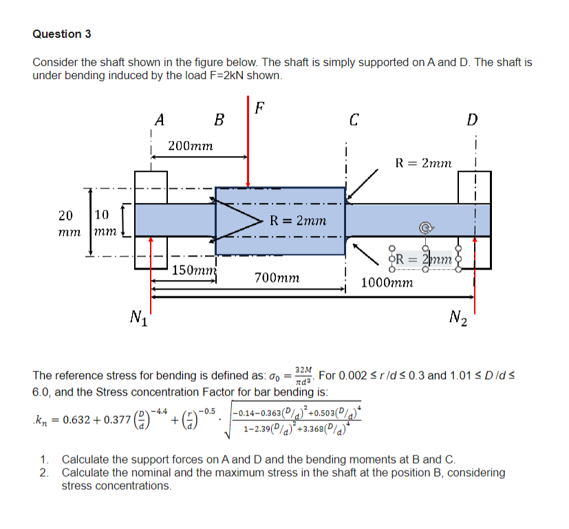
Question 3 Consider the shaft shown in the figure below. The shaft is simply supported on A and D. The shaft is under bending

Question 3 Consider the shaft shown in the figure below. The shaft is simply supported on A and D. The shaft is under bending induced by the load F-2kN shown. F 20 10 mm mm N A B 200mm 150mm R = 2mm -4.4 .K = 0.632 +0.377 (2)* + (7)-0.5. kn 700mm C R = 2mm OR 1000mm -0.14-0.363(P/ +0.503 (P/)* 1-2.39 (P/a) +3.368 (P/a)* = 2mm D 32M The reference stress for bending is defined as: %0 = For 0.002 r/d 0.3 and 1.01 D/ds 6.0, and the Stress concentration Factor for bar bending is: d N 2. 1. Calculate the support forces on A and D and the bending moments at B and C. Calculate the nominal and the maximum stress in the shaft at the position B, considering stress concentrations.
Step by Step Solution
There are 3 Steps involved in it
Step: 1

Get Instant Access to Expert-Tailored Solutions
See step-by-step solutions with expert insights and AI powered tools for academic success
Step: 2

Step: 3

Ace Your Homework with AI
Get the answers you need in no time with our AI-driven, step-by-step assistance
Get StartedRecommended Textbook for
Shigleys Mechanical Engineering Design
Authors: Richard G. Budynas, J. Keith Nisbett
9th edition
77679520, 73529281, 1259986241, 978-0077679521, 9780073529288, 9781259986246, 978-1121345317
Students also viewed these Mechanical Engineering questions
Question
Answered: 1 week ago
Question
Answered: 1 week ago
Question
Answered: 1 week ago
Question
Answered: 1 week ago
Question
Answered: 1 week ago
Question
Answered: 1 week ago
Question
Answered: 1 week ago
Question
Answered: 1 week ago
Question
Answered: 1 week ago
Question
Answered: 1 week ago
Question
Answered: 1 week ago
Question
Answered: 1 week ago
Question
Answered: 1 week ago
Question
Answered: 1 week ago
Question
Answered: 1 week ago
Question
Answered: 1 week ago
Question
Answered: 1 week ago
Question
Answered: 1 week ago
Question
Answered: 1 week ago
View Answer in SolutionInn App


