

Question
Read the question twice, There are multiple logic table related question already in Chegg This one is not same. Please double check and solve only
Read the question twice, There are multiple logic table related question already in Chegg
This one is not same. Please double check and solve only you are confident.
***DO NOT copy previous answers.
***I along with my other course mates will put dislike if you do so.
*** I repeat Read the question twice
this question isn't same as previously uploaded...
*** Your correct answer will be appreciated. HELP ME OUT
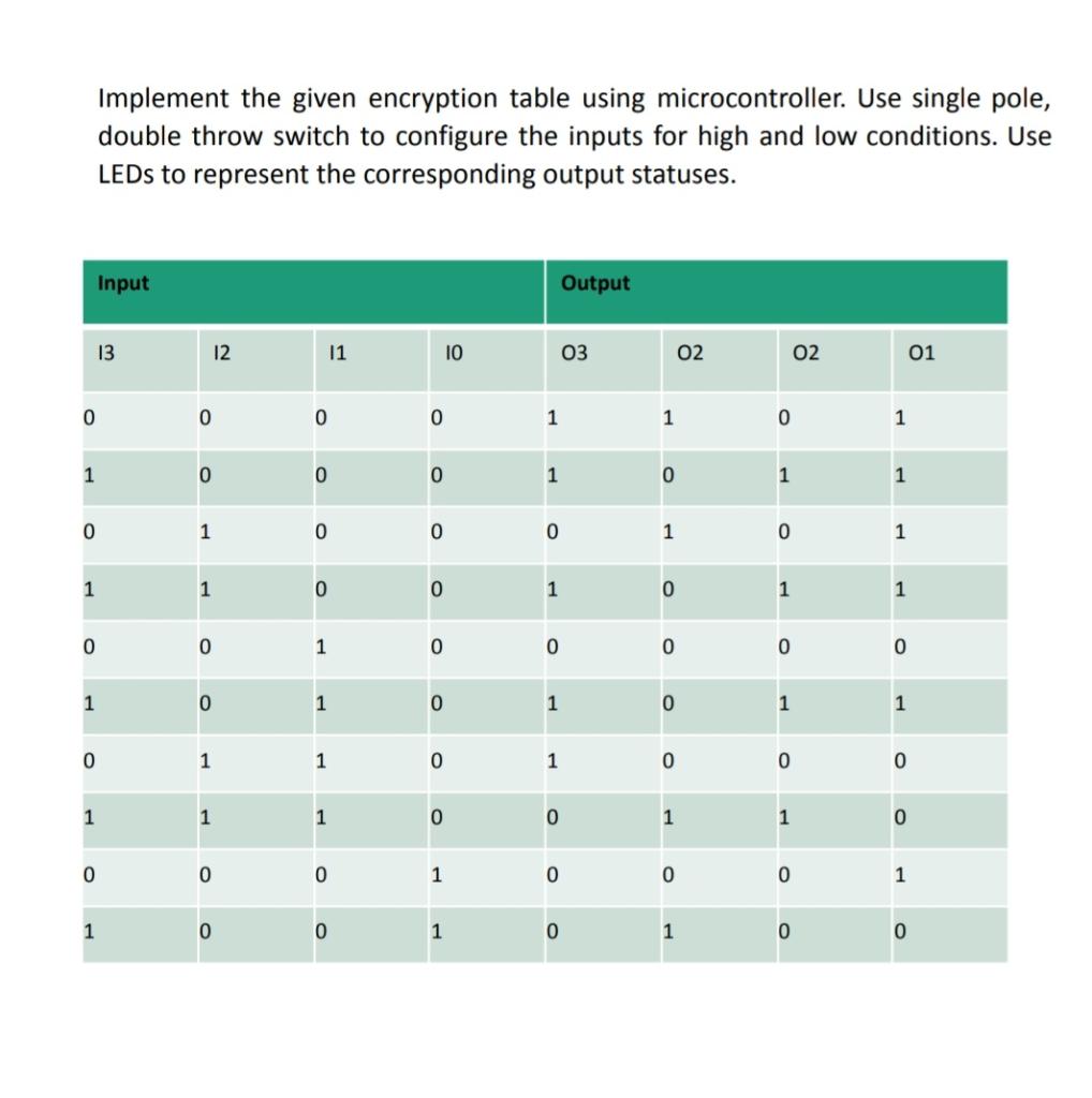
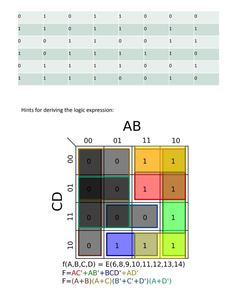
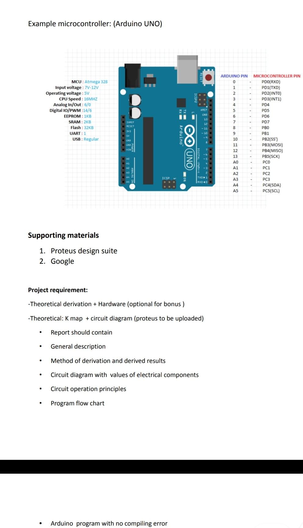
Implement the given encryption table using microcontroller. Use single pole, double throw switch to configure the inputs for high and low conditions. Use LEDs to represent the corresponding output statuses. Input Output 13 12 11 10 03 02 02 01 0 0 0 0 1 1 0 1 1 0 0 0 1 0 1 1 0 1 0 0 0 1 0 1 1 1 0 0 1 0 1 1 O 0 1 0 0 0 0 0 1 0 1 0 1 0 1 1 0 1 1 0 1 0 0 0 1 1 1 0 0 1 1 0 0 0 0 1 0 0 0 1 1 0 0 1 0 1 0 0 0 1 0 1 1 0 0 0 1 1 0 1 1 0 1 1 0 0 1 1 0 0 1 1 1 0 1 1 1 1 1 0 0 1 1 1 1 0 0 1 1 1 1 1 0 0 1 0 Hints for deriving the logic expression: AB 00 01 11 10 00 0 1 1 0 1 1 01 CD 11 0 1 10 1 1 1 = f(A,B,C,D) = E(6,8,9,10,11,12,13,14) F=AC'+AB'+BCD'+AD' F=(A+B)(A+C)(B'+C'+D')(A+D') Example microcontroller: (Arduino UNO) ARDUINO PIN 0 1 2 3 4 MCU: Atmega 328 Input voltage: 7V-12V Operating voltage: 5V CPU Speed : 16MHZ Analog In/Out: 6/0 Digital 10/PWM :14/6 EEPROM : IKB SRAM : 2KB Flash : 32KB UART: 1 USB: Regular AREF 5 6 7 TORET RESET 33 SV Arduino MICROCONTROLLER PIN PDO(RXD) PD1(TXD) PD2(INTO) PD3(INT1) PD4 PD5 PD6 PD7 PBO PB1 PB2(SS') PB3(MOSI) PB4(MISO) PB5(SCK) PCO PC1 PC2 PC3 PC4(SDA) PC5(SCL) GND OO UNO 8 9 10 11 12 13 0 A1 A2 A3 A4 A5 ICSP Supporting materials 1. Proteus design suite 2. Google Project requirement: -Theoretical derivation + Hardware (optional for bonus ) -Theoretical: K map + circuit diagram (proteus to be uploaded) Report should contain . General description . Method of derivation and derived results Circuit diagram with values of electrical components . Circuit operation principles . Program flow chart . Arduino program with no compiling errorStep by Step Solution
There are 3 Steps involved in it
Step: 1

Get Instant Access to Expert-Tailored Solutions
See step-by-step solutions with expert insights and AI powered tools for academic success
Step: 2

Step: 3
Ace Your Homework with AI
Get the answers you need in no time with our AI-driven, step-by-step assistance
Get Started
Machine Learning And Knowledge Discovery In Databases European Conference Ecml Pkdd 2014 Nancy France September 15 19 2014 Proceedings Part I Lnai 8724
Authors: Toon Calders ,Floriana Esposito ,Eyke Hullermeier ,Rosa Meo
2014th Edition