Question
Scan a Key from a need help for Matrix Keypad for TM4C123G, help me finish the code for case part please, I do not know


 Scan a Key from a need help for Matrix Keypad for TM4C123G, help me finish the code for case part please, I do not know how to do this type of the code.
#include
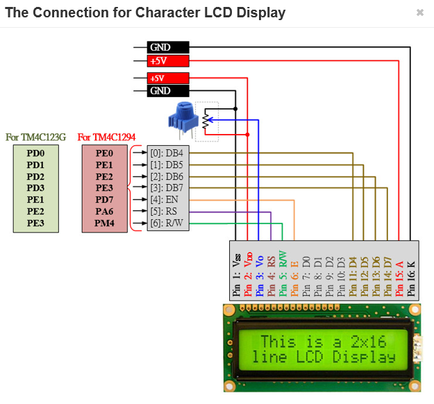
char str[100]; char ReadKeyPad(); char ch; int main(void) { PEZOBJ_LCD lcd; uint16_t i = 0; // GPIO Initialization and Configuration // 1. Enable Clock on GPIOs SYSCTL->RCGCGPIO |= 0x00; // allow time for clock to stabilize while ((SYSCTL->PRGPIO & 0x1B) != 0x1B) {}; // 2. Unlock PD7 and/or PF0 for TM4C 123G // 3. Config AMSEL to disable analog function GPIOA ->AMSEL=0x00; GPIOB ->AMSEL = 0x00; GPIOD -> AMSEL = 0x00; GPIOE -> AMSEL =0x00; // 4. Config PCTL to select 0-GPIO GPIOA->PCTL=0x00; GPIOB->PCTL=0x00; GPIOD->PCTL=0x00; GPIOE->PCTL=0x00; // 5. Set AFSEL bits to 0 GPIOA -> AFSEL =0x00; GPIOB -> AFSEL =0x00;GPIOD -> AFSEL =0x00;GPIOE -> AFSEL =0x00; // 6. Set DIR to 0 for input, 1 for output GPIOE ->DIR =0x0F; GPIOD-> DIR=0x3E; GPIOB->DIR=0x03; GPIOA->DIR= 0x00; // 7. Set PUR/PDR/ODR bits to 1 to enable internal pull-up/-down resistir and/or open-drain GPIOB->PUR=0x03; GPIOE->PUR=0x30; GPIOB->PUR=0X10; GPIOA->PUR=0xE0; // 8. Set DEN bits to 1 to enable all pins GPIOA->DEN=0xE0; GPIOD->DEN=0x0F; GPIOE->DEN= 0x3E; GPIOB->DEN=0x13; lcd = ezLCD_Create(); ezLCD_Connect_DataPort(lcd, GPIOD, PIN_3_0); ezLCD_Connect_ENPin(lcd, GPIOE, PIN1); ezLCD_Connect_RSPin(lcd, GPIOE, PIN2); ezLCD_Connect_RWPin(lcd, GPIOE, PIN3); ezLCD_Start(lcd); ezLCD_ClearDisplay(lcd); ezLCD_Position(lcd, 1, 0); ezLCD_PrintString(lcd, "HELLO");
while(1){ char ch = ReadKeyPad(); if (ch == '*'){ i *= 100; ezLCD_ClearDisplay(lcd); } if (ch == '#') i = 0; if (ch >='0' && ch
char ReadKeyPad() { int row, col;
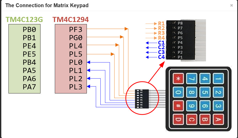
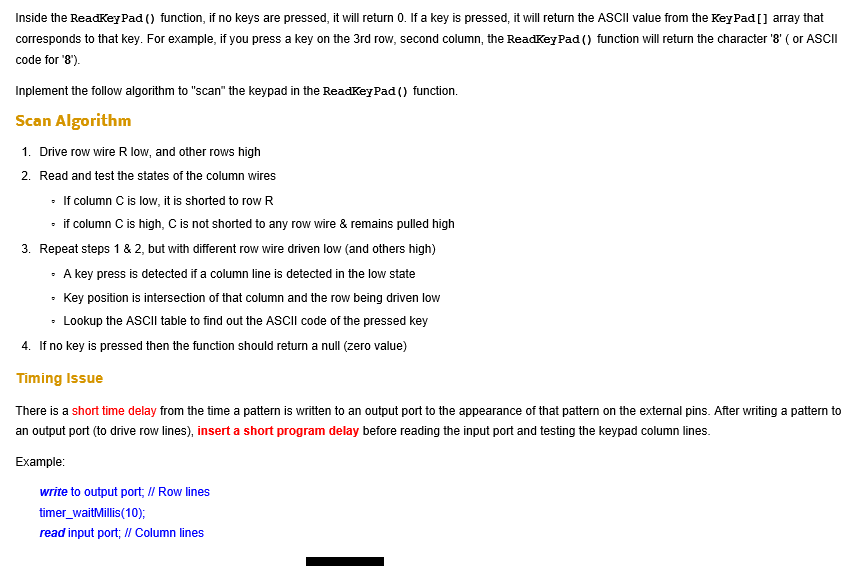
char key =0; for (row =0; row 0, R2 ,R3, R4=>1 break; case 2: break;
case 3: break ; } timer_waitMillis(10); col = (( GPIOB ->DATA & 0x10) >> 4) ; if (!(col& 0x01)) key =KeyPad [row] [1] ; // check c1 //check c2 // check c3 // check C4 if (key) break; } }
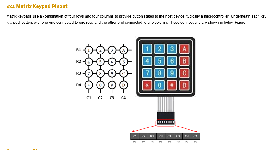
x4 Matrix Keypad Pinout Matrix keypads use a combination of four rows and four columns to provide button states to the host device, typically a microcontroller. Underneath each key is a pushbutton, with one end connected to one row, and the other end connected to one column. These connections are shown in below Figure R2 456 B 4 C1 C2 C3 C4 R1 R2 R3 R4 C1 C2 C3 C4 P7 P6 PS P4 P3P2P1 x4 Matrix Keypad Pinout Matrix keypads use a combination of four rows and four columns to provide button states to the host device, typically a microcontroller. Underneath each key is a pushbutton, with one end connected to one row, and the other end connected to one column. These connections are shown in below Figure R2 456 B 4 C1 C2 C3 C4 R1 R2 R3 R4 C1 C2 C3 C4 P7 P6 PS P4 P3P2P1
Step by Step Solution
There are 3 Steps involved in it
Step: 1

Get Instant Access to Expert-Tailored Solutions
See step-by-step solutions with expert insights and AI powered tools for academic success
Step: 2

Step: 3

Ace Your Homework with AI
Get the answers you need in no time with our AI-driven, step-by-step assistance
Get Started


