

Question
*****Scheme is the coding language used, specifically in Dr. Racket****************** 1 Write three Scheme procedures to simulate these three gates: AND, OR, and XOR, shown
*****Scheme is the coding language used, specifically in Dr. Racket******************
1 Write three Scheme procedures to simulate these three gates: AND, OR, and XOR, shown in the diagram in Figure 1. Test your procedures using all possible input combinations. (6 points)
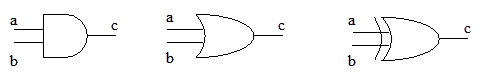
Figure 1. Logic gates AND, OR, and XOR
2 Define a Scheme procedure (bitAdder x a b) to simulate the logic design given in the diagram in Figure 2. The procedure must call the gate procedures that you defined in Question 1 and must return a pair with two elements '(s . c), where s is the binary sum of a, b, and x, while c is the carry-out. You will implement the procedure in three steps using three procedures, as listed below.
2.1 Write a procedure (sum-bit x a b) to generate the result bit s. (5 points)
2.2 Write a procedure (carry-out x a b) to generate the carry-out bit c. (5 points)
2.3 Write a procedure (bitAdder x a b) to generate the pair out put (s . c). (4 points)

Figure 2. The logic design of a one-bit adder
Verify your procedure by exhaustive testing: Use all valid inputs to test the procedure. There are eight valid inputs:
(bitAdder 0 0 0)
(bitAdder 0 0 1)
(bitAdder 0 1 0)
(bitAdder 0 1 1)
(bitAdder 1 0 0)
(bitAdder 1 0 1)
(bitAdder 1 1 0)
(bitAdder 1 1 1)
The expected outputs are as follows:
;(0 . 0)
;(1 . 0)
;(1 . 0)
;(0 . 1)
;(1 . 0)
;(0 . 1)
;(0 . 1)
;(1 . 1)
Append your test outputs at the end of your procedures. Put the outputs as comments, so that your procedures can execute without removing these outputs.
3 The diagram in Figure 3 shows the design of an n-bit adder using n one-bit adders, where n = 32 in the diagram. The carry-out of bit-i is the carry-in of bit i+1, where carry-in of bit 0 is 0. The procedure should have three parameters: A, B, and n, where A and B are two lists representing two inputs numbers, and n is the length of A and B: (n-bit-adder A B n). Two solutions are acceptable: Follow the design in Figure 3, and follow the binary addition algorithm given in the lecture slides. In both case, you must call at one of the procedures that you defined in Question 2.
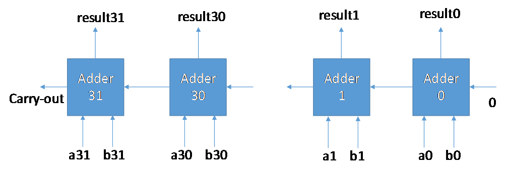
Figure 3. The design of a 32-bit adder
3.1 Define a procedure (tail lst), which returns the last element of lst. (4 points)
3.2 Define a procedure (rmtail lst), which returns the list without the last element of lst. (4 points)
3.3 Follow the fantastic-four abstract approach to design your recursive solution by explaining: (1) What is the size-n problem of your procedure? (2) What are the stopping condition and its return value? (3) What is the size-(n-1) problem? What are the steps to construct the size-n problem solution from the size-(n-1) solution. Write the answers as comments in the program. (4 points)
3.4 Follow the four steps to implement the n-bit adder, and design a test plan to test the program. You must call the bit-adder recursively to implement the program. (14 points)
Note: your (n-bit-adder A B n) should call a recursive procedure, e.g., (recursiveAdd A B c), where c is carry. You can follow the lecture slides to write these two procedures. However, you cannot use (quotient t 2) and (remainder t 2). Instead, you should call your (bit-adder (tail A) (tail B) c). You can use (car (bit-adder (tail A) (tail B) c)) and (cdr (bit-adder (tail A) (tail B) c)) to obtain the sum and carry, respectively.
3.5 Write a procedure to convert your result into the required output format. (4 points)
Test your program using the following test cases and submit the outputs.
(define X1 '(0 0 0 0 0 0 0 0 0 0 0 0 0 0 0 0 0 0 0 0 0 0 0 0 0 0 0 0 0 0 0 0) )
(define X2 '(1 1 1 1 1 1 1 1 1 1 1 1 1 1 1 1 1 1 1 1 1 1 1 1 1 1 1 1 1 1 1 1) )
(define X3 '(0 1 0 1 0 1 0 1 0 1 0 1 0 1 0 1 0 1 0 1 0 1 0 1 0 1 0 1 0 1 0 1) )
(define X4 '(1 0 1 0 1 0 1 0 1 0 1 0 1 0 1 0 1 0 1 0 1 0 1 0 1 0 1 0 1 0 1 0) )
(define X5 '(0 1 0 1 0 1 0 1 0 1 0 1 0 1 1 1 0 1 0 1 0 1 0 1 0 1 0 1 0 1 1 1) )
(define X6 '(1 0 1 0 1 0 1 0 1 0 1 0 1 0 1 1 1 0 1 0 1 0 1 0 1 0 1 0 1 0 1 1) )
(n-bit-adder X1 X2 32)
(n-bit-adder X3 X4 32)
(n-bit-adder X5 X6 32)
(n-bit-adder X2 X3 32)
(n-bit-adder X4 X5 32)
(n-bit-adder X1 X6 32)
The expect outputs and format are as follows:
((0) 1 1 1 1 1 1 1 1 1 1 1 1 1 1 1 1 1 1 1 1 1 1 1 1 1 1 1 1 1 1 1 1)
((0) 1 1 1 1 1 1 1 1 1 1 1 1 1 1 1 1 1 1 1 1 1 1 1 1 1 1 1 1 1 1 1 1)
((1) 0 0 0 0 0 0 0 0 0 0 0 0 0 0 1 1 0 0 0 0 0 0 0 0 0 0 0 0 0 0 1 0)
((1) 0 1 0 1 0 1 0 1 0 1 0 1 0 1 0 1 0 1 0 1 0 1 0 1 0 1 0 1 0 1 0 0)
((1) 0 0 0 0 0 0 0 0 0 0 0 0 0 0 1 0 0 0 0 0 0 0 0 0 0 0 0 0 0 0 0 1)
((0) 1 0 1 0 1 0 1 0 1 0 1 0 1 0 1 1 1 0 1 0 1 0 1 0 1 0 1 0 1 0 1 1)
Where, the first element is the carry-out of the addition. If the carry-out is (1), it represents an overflow in the adder. The remaining elements of the list are the sum.
a a a c b c --b c -bStep by Step Solution
There are 3 Steps involved in it
Step: 1

Get Instant Access to Expert-Tailored Solutions
See step-by-step solutions with expert insights and AI powered tools for academic success
Step: 2

Step: 3
Ace Your Homework with AI
Get the answers you need in no time with our AI-driven, step-by-step assistance
Get Started
Making Databases Work The Pragmatic Wisdom Of Michael Stonebraker
Authors: Michael L. Brodie
1st Edition
1947487167, 978-1947487161