Show the design processes of the tail-light control unit in terms of state tables or state graphs, state assignment, setting the clock period, and circuit realization (i.e. logic gates and flip-flops). Describe the steps taken to minimize the number of logic gates and flip-flops.

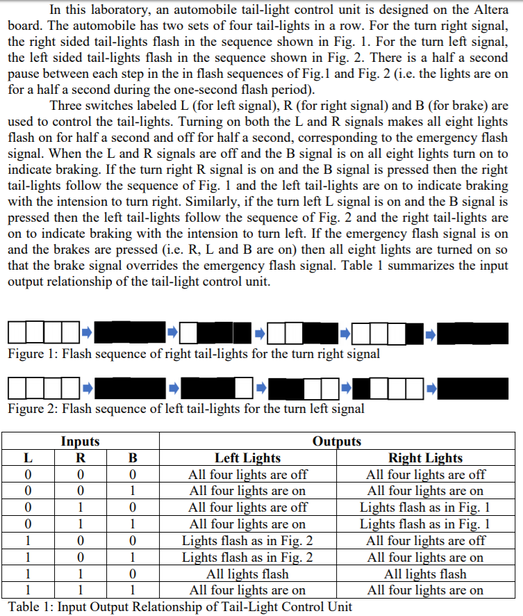
In this laboratory, an automobile tail-light control unit is designed on the Altera board. The automobile has two sets of four tail-lights in a row. For the turn right signal, the right sided tail-lights flash in the sequence shown in Fig. 1. For the turn left signal, the left sided tail-lights flash in the sequence shown in Fig. 2. There is a half a second pause between each step in the in flash sequences of Fig.1 and Fig. 2 (i.e. the lights are on for a half a second during the one-second flash period) Three switches labeled L (for left signal), R (for right signal) and B (for brake) are used to control the tail-lights. Turning on both the L and R signals makes all eight lights flash on for half a second and off for half a second, corresponding to the emergency flash signal. When the L and R signals are off and the B signal is on all eight lights turn on to indicate braking. If the turn right R signal is on and the B signal is pressed then the right tail-lights follow the sequence of Fig. 1 and the left tail-lights are on to indicate braking with the intension to turn right. Similarly, if the turn left L signal is on and the B signal is pressed then the left tail-lights follow the sequence of Fig. 2 and the right tail-lights are on to indicate braking with the intension to turn left. If the emergency flash signal is on and the brakes are pressed (i.e. R, L and B are on) then all eight lights are turned on so that the brake signal overrides the emergency flash signal. Table 1 summarizes the input output relationship of the tail-light control unit. Figure 1: Flash sequence of right tail-lights for the turn right signal Figure 2: Flash sequence of left tail-lights for the turn left signal Inputs Outputs Left Lights All four lights are off All four lights are on All four lights are off All four lights are on Lights flash as in Fig. 2 Lights flash as in Fig. 2 All lights flash All four lights are on Right Lights All four lights are off All four lights are on Lights flash as in Fig. 1 Lights flash as in Fig. 1 All four lights are off All four lights are on All lights flash All four lights are on 0 0 0 0 0 0 0 0 Table 1: Input Output Relationship of Tail-Light Control Unit In this laboratory, an automobile tail-light control unit is designed on the Altera board. The automobile has two sets of four tail-lights in a row. For the turn right signal, the right sided tail-lights flash in the sequence shown in Fig. 1. For the turn left signal, the left sided tail-lights flash in the sequence shown in Fig. 2. There is a half a second pause between each step in the in flash sequences of Fig.1 and Fig. 2 (i.e. the lights are on for a half a second during the one-second flash period) Three switches labeled L (for left signal), R (for right signal) and B (for brake) are used to control the tail-lights. Turning on both the L and R signals makes all eight lights flash on for half a second and off for half a second, corresponding to the emergency flash signal. When the L and R signals are off and the B signal is on all eight lights turn on to indicate braking. If the turn right R signal is on and the B signal is pressed then the right tail-lights follow the sequence of Fig. 1 and the left tail-lights are on to indicate braking with the intension to turn right. Similarly, if the turn left L signal is on and the B signal is pressed then the left tail-lights follow the sequence of Fig. 2 and the right tail-lights are on to indicate braking with the intension to turn left. If the emergency flash signal is on and the brakes are pressed (i.e. R, L and B are on) then all eight lights are turned on so that the brake signal overrides the emergency flash signal. Table 1 summarizes the input output relationship of the tail-light control unit. Figure 1: Flash sequence of right tail-lights for the turn right signal Figure 2: Flash sequence of left tail-lights for the turn left signal Inputs Outputs Left Lights All four lights are off All four lights are on All four lights are off All four lights are on Lights flash as in Fig. 2 Lights flash as in Fig. 2 All lights flash All four lights are on Right Lights All four lights are off All four lights are on Lights flash as in Fig. 1 Lights flash as in Fig. 1 All four lights are off All four lights are on All lights flash All four lights are on 0 0 0 0 0 0 0 0 Table 1: Input Output Relationship of Tail-Light Control Unit


