Answered step by step
Verified Expert Solution
Link Copied!

Question

1 Approved Answer

Show the state graph of the control unit FSM. Show where in the datapth you are checking the condition. B) Fill-in the control word table

Show the state graph of the control unit FSM. Show where in the datapth you are checking the condition. B) Fill-in the control word table the control signals to be asserted to the Datapath inputs 0 through 15 in every cycle. The Table is provided in the solution section for your convenience.

There are two algorithms, and you can use either of these two. The second one needs only a one wire to check the condition, whereas the second one needs 8-input NOR gate). At this point, say, we dont care about this difference Just copy /paste the algorithm you used into your solution, so I know which one you followed. Algorithm 1: count = 0 input n while n > 0: { count = count + 1 n = n & (n-1) } output count Algorithm 2: (checking the least significant bit for 1 and adding it to count, easy condition logic, as it is a wire) count =0 Input n while n { if LSB(n) =1 { count=count+1 n=n>>1 } output count Grading contract: State graph: 1 point; Control Word Table 2 points
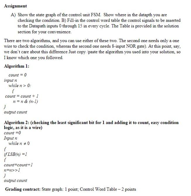
image text in transcribed

A) Show the state graph of the control unit FSM. Show where in the datapth you are checking the condition. B) Fill-in the control word table the control signals to be asserted to the Datapath inputs 0 through 15 in every cycle. The Table is provided in the solution section for your convenience. There are two algorithms, and you can use either of these two. The second one needs only a one wire to check the condition, whereas the second one needs 8-input NOR gate). At this point, say, we don't care about this difference Just copy/paste the algorithm you used into your solution, so I know which one you followed. Algorithm 1: count =0 input n while n>0 : {count=count+1n=n&(n1) outputcount 3 Algorithm 2: (checking the least significant bit for 1 and adding it to count, easy condition logic, as it is a wire) count =0 Input n while n=0 \{ if LSB(n)=1 \{ count = count +1 n=n>>1 \} output count Grading contract: State graph: 1 point; Control Word Table 2 points A) Show the state graph of the control unit FSM. Show where in the datapth you are checking the condition. B) Fill-in the control word table the control signals to be asserted to the Datapath inputs 0 through 15 in every cycle. The Table is provided in the solution section for your convenience. There are two algorithms, and you can use either of these two. The second one needs only a one wire to check the condition, whereas the second one needs 8-input NOR gate). At this point, say, we don't care about this difference Just copy/paste the algorithm you used into your solution, so I know which one you followed. Algorithm 1: count =0 input n while n>0 : {count=count+1n=n&(n1) outputcount 3 Algorithm 2: (checking the least significant bit for 1 and adding it to count, easy condition logic, as it is a wire) count =0 Input n while n=0 \{ if LSB(n)=1 \{ count = count +1 n=n>>1 \} output count Grading contract: State graph: 1 point; Control Word Table 2 points

Step by Step Solution

There are 3 Steps involved in it

Step: 1

blur-text-image

Get Instant Access to Expert-Tailored Solutions

See step-by-step solutions with expert insights and AI powered tools for academic success

Step: 2

blur-text-image_2

Step: 3

blur-text-image_3

Ace Your Homework with AI

Get the answers you need in no time with our AI-driven, step-by-step assistance

Get Started

Recommended Textbook for

Temporal Databases Research And Practice Lncs 1399

Authors: Opher Etzion ,Sushil Jajodia ,Suryanarayana Sripada

1st Edition

3540645195, 978-3540645191

More Books

Students also viewed these Databases questions

Question

=+what were the US and the UR?

Answered: 1 week ago

Question

Give three examples of access control in a POS system.

Answered: 1 week ago

Question

Define Administration?

Answered: 1 week ago