Answered step by step
Verified Expert Solution
Question
1 Approved Answer
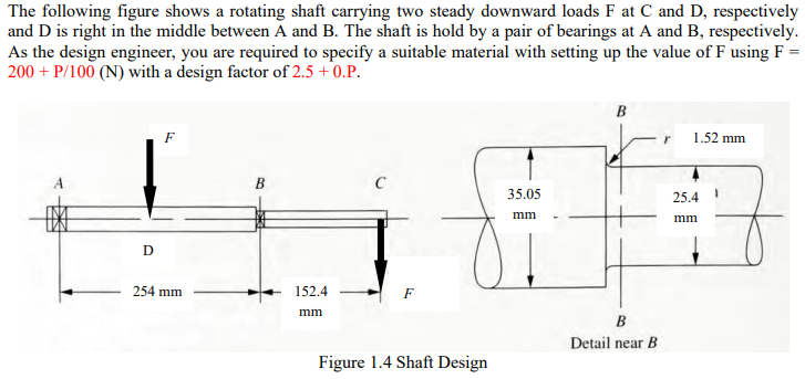
shows a rotating shaft carrying two steady downward loads F at C and D, respectively and D is right in the middle between A and
shows a rotating shaft carrying two steady downward loads F at C and D, respectively and D is right in the middle between A and B. The shaft is held by a pair of bearings at A and B, respectively. As the design engineer, you are required to specify a suitable material for material selection with setting up the value of F using F = 200 + P/100 (N) with a design factor of 2.5 + 0.P.

The following figure shows a rotating shaft carrying two steady downward loads F at C and D, respectively and D is right in the middle between A and B. The shaft is hold by a pair of bearings at A and B, respectively. As the design engineer, you are required to specify a suitable material with setting up the value of F using F = 200+ P/100 (N) with a design factor of 2.5 +0.P. D F B r 1.52 mm B C 35.05 25.4 mm mm 254 mm 152.4 mm Figure 1.4 Shaft Design B Detail near B
Step by Step Solution
There are 3 Steps involved in it
Step: 1
Solutions Shaft Design Attached below is the design of shaft The design shows Torque Diagram ...
Get Instant Access to Expert-Tailored Solutions
See step-by-step solutions with expert insights and AI powered tools for academic success
Step: 2

Step: 3

Ace Your Homework with AI
Get the answers you need in no time with our AI-driven, step-by-step assistance
Get Started


