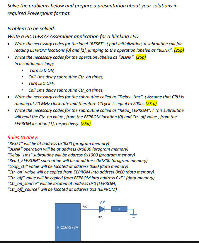
Solve the problems below and prepare a presentation about your solutions in required Powerpoint format. . Problem to be solved: Write a PIC16F877 Assembler application for a blinking LED. Write the necessary codes for the label RESET". ( port initialization, a subroutine call for reading EEPROM locations [0] and [1], jumping to the operation labeled as BLINK. (25p) Write the necessary codes for the operation labeled as BLINK". (25p) In a continuous loop; Turn LED ON, Call 1ms delay subroutine Ctr_on times, Turn LED OFF, Call 1ms delay subroutine Ctr_on times, Write the necessary codes for the subroutine called as Delay_1ms. (Assume that CPU is running at 20 MHz clock rate and therefore 1Tcycle is equal to 200ns.(25 p) Write the necessary codes for the subroutine called as Read_EEPROM. (This subroutine will read the Ctr_on value, from the EEPROM location [0] and Ctr_off value , from the EEPROM location (1), respectively. (25p) Rules to obey: RESET will be at address 0x0000 (program memory) "BLINK" operation will be at address Ox0800 (program memory) "Delay_1ms" subroutine will be address 0x1000 (program memory) "Read_EEPROM" subroutine will be at address 0x1800 (program memory) "Loop_ctr" value will be located at address 0x60 (data memory) "Ctr_on" value will be copied from EEPROM into address OxE0 (data memory) "Ctr_off" value will be copied from EEPROM into address OxE1 (data memory) "Ctr_on_source" will be located at address OxO (EEPROM) "Ctr_off_source" will be located at address 0x1 (EEPROM) RAO R LED PIC16F877A Solve the problems below and prepare a presentation about your solutions in required Powerpoint format. . Problem to be solved: Write a PIC16F877 Assembler application for a blinking LED. Write the necessary codes for the label RESET". ( port initialization, a subroutine call for reading EEPROM locations [0] and [1], jumping to the operation labeled as BLINK. (25p) Write the necessary codes for the operation labeled as BLINK". (25p) In a continuous loop; Turn LED ON, Call 1ms delay subroutine Ctr_on times, Turn LED OFF, Call 1ms delay subroutine Ctr_on times, Write the necessary codes for the subroutine called as Delay_1ms. (Assume that CPU is running at 20 MHz clock rate and therefore 1Tcycle is equal to 200ns.(25 p) Write the necessary codes for the subroutine called as Read_EEPROM. (This subroutine will read the Ctr_on value, from the EEPROM location [0] and Ctr_off value , from the EEPROM location (1), respectively. (25p) Rules to obey: RESET will be at address 0x0000 (program memory) "BLINK" operation will be at address Ox0800 (program memory) "Delay_1ms" subroutine will be address 0x1000 (program memory) "Read_EEPROM" subroutine will be at address 0x1800 (program memory) "Loop_ctr" value will be located at address 0x60 (data memory) "Ctr_on" value will be copied from EEPROM into address OxE0 (data memory) "Ctr_off" value will be copied from EEPROM into address OxE1 (data memory) "Ctr_on_source" will be located at address OxO (EEPROM) "Ctr_off_source" will be located at address 0x1 (EEPROM) RAO R LED PIC16F877A