

Answered step by step
Verified Expert Solution
Question
1 Approved Answer
SULIT (BMCG 2212) English Version - Q1 Timing diagrams are used in digital electronics to show the operation of various circuits through graphs. In most
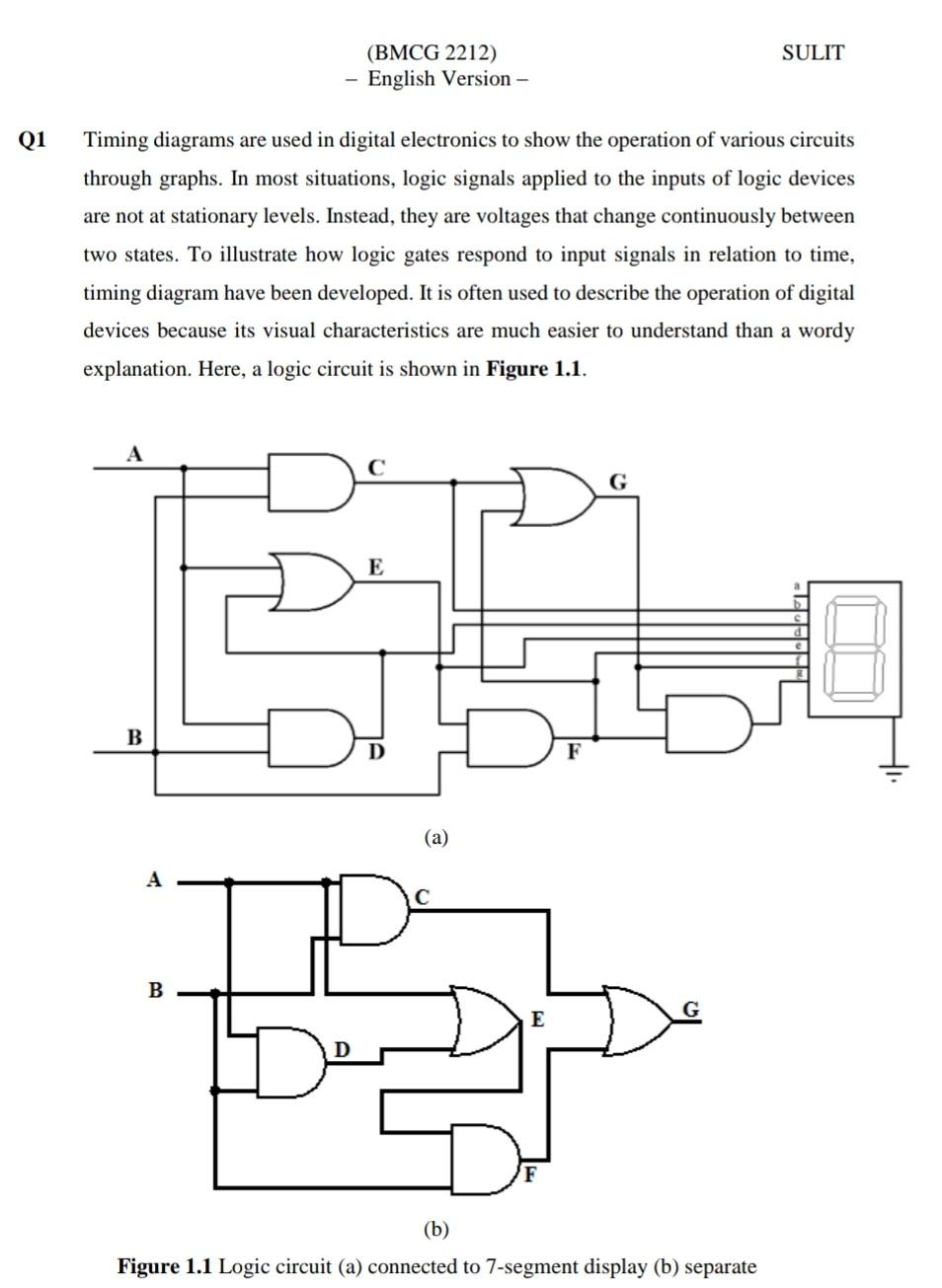
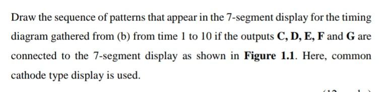
SULIT (BMCG 2212) English Version - Q1 Timing diagrams are used in digital electronics to show the operation of various circuits through graphs. In most situations, logic signals applied to the inputs of logic devices are not at stationary levels. Instead, they are voltages that change continuously between two states. To illustrate how logic gates respond to input signals in relation to time, timing diagram have been developed. It is often used to describe the operation of digital devices because its visual characteristics are much easier to understand than a wordy explanation. Here, a logic circuit is shown in Figure 1.1. A ELLI B (a) B (b) Figure 1.1 Logic circuit (a) connected to 7-segment display (b) separate Draw the sequence of patterns that appear in the 7-segment display for the timing diagram gathered from (b) from time 1 to 10 if the outputs C, D, E, F and G are connected to the 7-segment display as shown in Figure 1.1. Here, common cathode type display is used
Step by Step Solution
There are 3 Steps involved in it
Step: 1

Get Instant Access to Expert-Tailored Solutions
See step-by-step solutions with expert insights and AI powered tools for academic success
Step: 2

Step: 3
Ace Your Homework with AI
Get the answers you need in no time with our AI-driven, step-by-step assistance
Get Started
Database Driven Web Sites
Authors: Mike Morrison, Joline Morrison
1st Edition
061901556X, 978-0619015565