Answered step by step
Verified Expert Solution
Question
1 Approved Answer
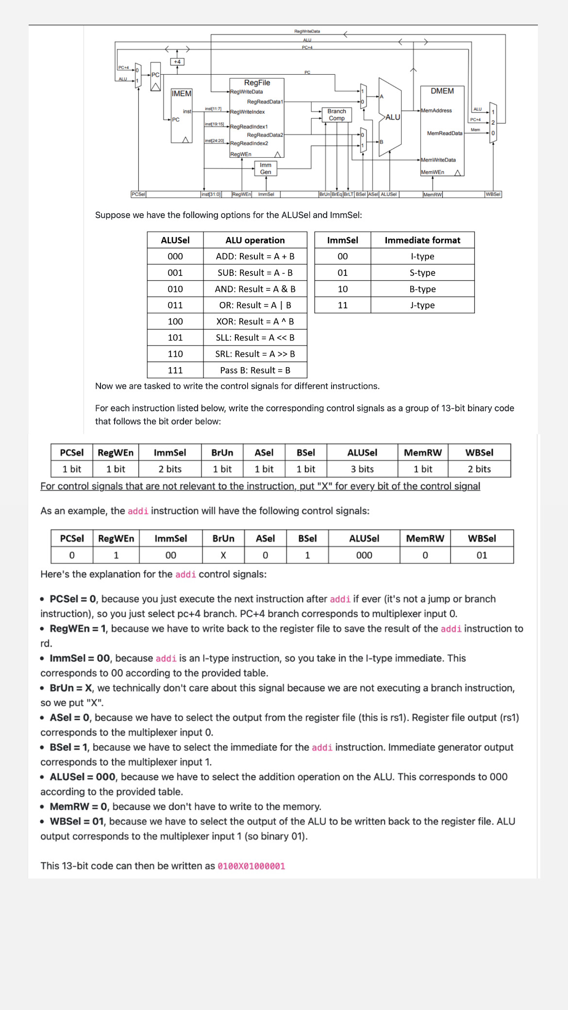
Suppose we have the following options for the ALUSel and ImmSel: Now we are tasked to write the control signals for different instructions. For each
Suppose we have the following options for the ALUSel and ImmSel:
Now we are tasked to write the control signals for different instructions.
For each instruction listed below, write the corresponding control signals as a group of bit binary code
that follows the bit order below:
For control signals that are not relevant to the instruction,put for every bit of the control signal
As an example, the addi instruction will have the following control signals:
Here's the explanation for the addi control signals:
PCSel because you just execute the next instruction after addi if ever its not a jump or branch
instruction so you just select pc branch. branch corresponds to multiplexer input
RegWEn because we have to write back to the register file to save the result of the addi instruction to
rd
ImmSel because addi is an ltype instruction, so you take in the ltype immediate. This
corresponds to according to the provided table.
BrUn we technically don't care about this signal because we are not executing a branch instruction,
so we put X
ASel because we have to select the output from the register file this is Register file output rs
corresponds to the multiplexer input
BSel because we have to select the immediate for the addi instruction. Immediate generator output
corresponds to the multiplexer input
ALUSel because we have to select the addition operation on the ALU. This corresponds to
according to the provided table.
MemRW because we don't have to write to the memory.
WBSel because we have to select the output of the ALU to be written back to the register file. ALU
output corresponds to the multiplexer input so binary
This bit code can then be written as Now it's your turn. For the following instructions, write the corresponding bit binary string without the b prefix that would correspond to the control signals to properly execute the instruction. All answers should be bits long.
Q: or instruction. Q: lw instruction. Q: sw instruction Q: jal instruction. Q: bgeu instruction assume that the branch condition is true in this case

Step by Step Solution
There are 3 Steps involved in it
Step: 1

Get Instant Access to Expert-Tailored Solutions
See step-by-step solutions with expert insights and AI powered tools for academic success
Step: 2

Step: 3

Ace Your Homework with AI
Get the answers you need in no time with our AI-driven, step-by-step assistance
Get Started


