Answered step by step
Verified Expert Solution
Question
1 Approved Answer
Switches operate within the scope of the data link layer Switch A GO/0/1 Host A IP: 10.1.1.1/24 MAC:00-01-02-03-04-AA G0/0/2 GO/0/3 Host B Host C
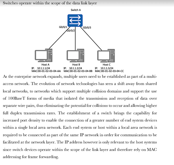
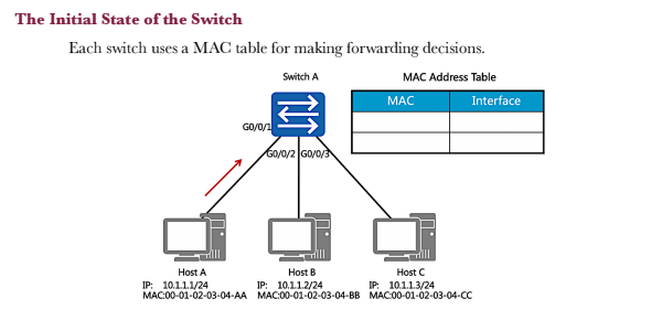
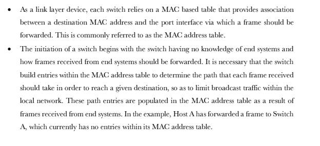
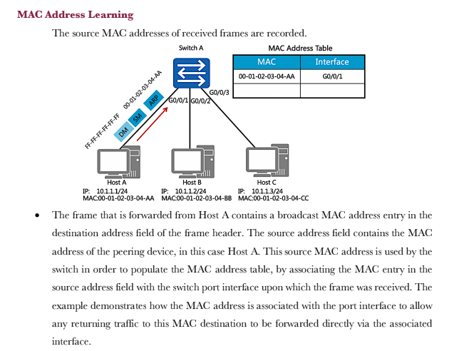

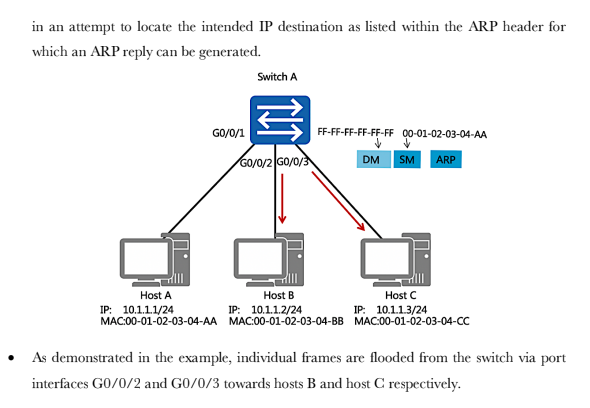
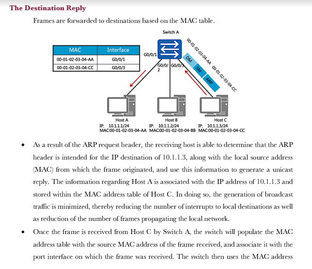

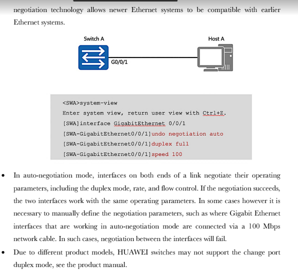
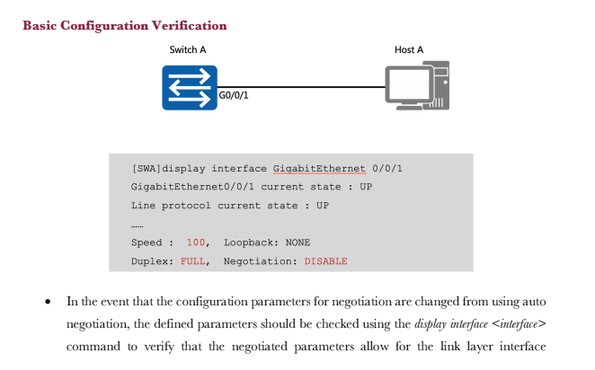


Switches operate within the scope of the data link layer Switch A GO/0/1 Host A IP: 10.1.1.1/24 MAC:00-01-02-03-04-AA G0/0/2 GO/0/3 Host B Host C IP: 10.1.1.2/24 IP: 10.1.1.3/24 MAC:00-01-02-03-04-BB MAC:00-01-02-03-04-CC As the enterprise network expands, multiple users need to be established as part of a multi- access network. The evolution of network technologies has seen a shift away from shared local networks, to networks which support multiple collision domains and support the use of 100BaseT forms of media that isolated the transmission and reception of data over separate wire pairs, thus eliminating the potential for collisions to occur and allowing higher full duplex transmission rates. The establishment of a switch brings the capability for increased port density to enable the connection of a greater number of end system devices within a single local area network. Each end system or host within a local area network is required to be connected as part of the same IP network in order for communication to be facilitated at the network layer. The IP address however is only relevant to the host systems since switch devices operate within the scope of the link layer and therefore rely on MAC addressing for frame forwarding. The Initial State of the Switch Each switch uses a MAC table for making forwarding decisions. Switch A MAC Address Table GO/0/1 G0/0/2 G0/0/3 MAC Interface Host A Host C Host B IP: 10.1.1.2/24 IP: 10.1.1.1/24 IP: 10.1.1.3/24 MAC:00-01-02-03-04-AA MAC:00-01-02-03-04-BB MAC:00-01-02-03-04-CC As a link layer device, each switch relies on a MAC based table that provides association between a destination MAC address and the port interface via which a frame should be forwarded. This is commonly referred to as the MAC address table. The initiation of a switch begins with the switch having no knowledge of end systems and how frames received from end systems should be forwarded. It is necessary that the switch build entries within the MAC address table to determine the path that each frame received should take in order to reach a given destination, so as to limit broadcast traffic within the local network. These path entries are populated in the MAC address table as a result of frames received from end systems. In the example, Host A has forwarded a frame to Switch A, which currently has no entries within its MAC address table. MAC Address Learning The source MAC addresses of received frames are recorded. Switch A ARP FF-FF-FF-FF-FF-FF 00-01-02-03-04-AA DM SM Host A IP: 10.1.1.1/24 MAC:00-01-02-03-04-AA GO/0/3 GO/0/1 G0/0/2 MAC Address Table MAC 00-01-02-03-04-AA Host C Host B IP: 10.1.1.2/24 IP: 10.1.1.3/24 MAC:00-01-02-03-04-BB MAC:00-01-02-03-04-CC Interface GO/0/1 The frame that is forwarded from Host A contains a broadcast MAC address entry in the destination address field of the frame header. The source address field contains the MAC address of the peering device, in this case Host A. This source MAC address is used by the switch in order to populate the MAC address table, by associating the MAC entry in the source address field with the switch port interface upon which the frame was received. The example demonstrates how the MAC address is associated with the port interface to allow any returning traffic to this MAC destination to be forwarded directly via the associated interface. Forwarding the First Data Frames destined for unknown link layer destinations are flooded. The general behavior of an ARP request involves the frame being flooded to all intended destinations primarily due to the MAC broadcast (FF-FF-FF-FF-FF-FF) that represents the current destination. The switch is therefore responsible for forwarding this frame out of every port interface with exception to the port interface on which the frame was received, in an attempt to locate the intended IP destination as listed within the ARP header for which an ARP reply can be generated. GO/0/1 Host A IP: 10.1.1.1/24 MAC:00-01-02-03-04-AA Switch A GO/0/2/GO/0/3 FF-FF-FF-FF-FF-FF 00-01-02-0 DM -02-03-04-AA SM ARP Host B Host C IP: 10.1.1.2/24 IP: 10.1.1.3/24 MAC:00-01-02-03-04-BB MAC:00-01-02-03-04-CC As demonstrated in the example, individual frames are flooded from the switch via port interfaces G0/0/2 and G0/0/3 towards hosts B and host C respectively. The Destination Reply Frames are forwarded to destinations based on the MAC table. Switch A MAC 00-01-02-03-04-AA 00-01-02-03-04-CC Interface GO/0/1 GO/0/3 GO/0/1 DM SM ARP 00-01-02-03-04-AA 00-01-02-03-04-CC GO/0/GO/0/ Host A Host B Host C IP: 10.1.1.1/24 IP: 10.1.1.2/24 IP: 10.1.1.3/24 MAC:00-01-02-03-04-AA MAC:00-01-02-03-04-BB MAC:00-01-02-03-04-CC As a result of the ARP request header, the receiving host is able to determine that the ARP header is intended for the IP destination of 10.1.1.3, along with the local source address (MAC) from which the frame originated, and use this information to generate a unicast reply. The information regarding Host A is associated with the IP address of 10.1.1.3 and stored within the MAC address table of Host C. In doing so, the generation of broadcast traffic is minimized, thereby reducing the number of interrupts to local destinations as well as reduction of the number of frames propagating the local network. Once the frame is received from Host C by Switch A, the switch will populate the MAC address table with the source MAC address of the frame received, and associate it with the port interface on which the frame was received. The switch then uses the MAC address Basic Configuration Early Ethernet systems operated based on a 10Mbps half-duplex mode and applied mechanisms such as CSMA/CD to ensure system stability. The transition to a twisted pair medium gave rise to the emergence of full-duplex Ethernet, which greatly improved Ethernet performance and meant two forms of duplex could be negotiated. The auto- negotiation technology allows newer Ethernet systems to be compatible with earlier Ethernet systems. Switch A GO/0/1 Host A system-view Enter system view, return user view with Ctrl+2. [SWA] interface GigabitEthernet 0/0/1 [SWA-GigabitEthernet0/0/1]undo [SWA-GigabitEthernet0/0/1] duplex full [SWA-GigabitEthernet0/0/1] speed 100 negotiation auto In auto-negotiation mode, interfaces on both ends of a link negotiate their operating parameters, including the duplex mode, rate, and flow control. If the negotiation succeeds, the two interfaces work with the same operating parameters. In some cases however it is necessary to manually define the negotiation parameters, such as where Gigabit Ethernet interfaces that are working in auto-negotiation mode are connected via a 100 Mbps network cable. In such cases, negotiation between the interfaces will fail. Due to different product models, HUAWEI switches may not support the change port duplex mode, see the product manual. Basic Configuration Verification Switch A GO/0/1 Host A [SWA] display interface GigabitEthernet 0/0/1 GigabitEthernet0/0/1 current state : UP Line protocol current state : UP Speed : 100, Loopback: NONE Duplex: FULL, Negotiation: DISABLE In the event that the configuration parameters for negotiation are changed from using auto negotiation, the defined parameters should be checked using the display interface command to verify that the negotiated parameters allow for the link layer interface negotiation to be successful. This is verified by the line protocol current state being displayed as UP. The displayed information reflects the current parameter settings for an interface. 1. If a switch records the source MAC address of a host device on a port interface, and the physical connection of the host is then changed to another port interface on the switch, what action would the switch take?
Step by Step Solution
There are 3 Steps involved in it
Step: 1

Get Instant Access to Expert-Tailored Solutions
See step-by-step solutions with expert insights and AI powered tools for academic success
Step: 2

Step: 3

Ace Your Homework with AI
Get the answers you need in no time with our AI-driven, step-by-step assistance
Get Started


