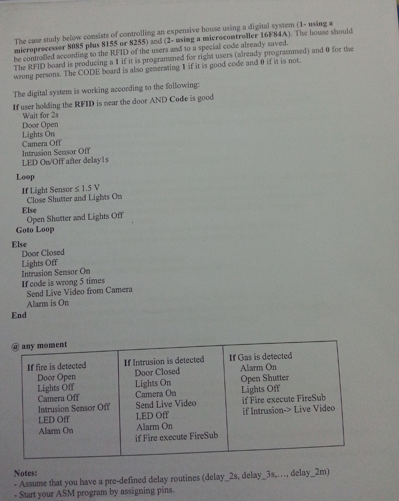
The case study below consists of controlling an expensive house using a digital system (1- using a microprocessor 8085 plus 8155 or 8255) and (2- using a microcontroller 16F84A). The house should be controlled according to the RFID of the users and to a special code already saved. The RFID board is producing a 1 if it is programmed for right users (already programmed) and 0 for the wrong persons. The CODE board is also generating 1 if it is good code and 0 if it is not. The digital system is working according to the following: If user holding the RFID is near the door AND Code is good Wait for 2s Door Open Lights On Camera Off Intrusion Sensor Off LED On/Off after delay 1s Loop If Light Sensor s 1.5 V Close Shutter and Lights On Else Open Shutter and Lights Off Goto Loop Else Door Closed Lights Off Intrusion Sensor On If code is wrong 5 times Send Live Video from Camera Alarm is On End @ any moment If fire is detected If Intrusion is detected If Gas is detected Door Open Lights Off Camera Off Intrusion Sensor OffSend Live Video LED Off Alarm On Door Closed Lights On Camera Orn Alarm On Open Shutter Lights Off if Fire execute FireSub if Intrusion-> Live Video LED Off Alarm On if Fire execute FireSub Notes: - Assume that you have a pre-defined delay routines (delay_2s, delay 3s,.., delay_2m) - Start your ASM program by assigning pins. The case study below consists of controlling an expensive house using a digital system (1- using a microprocessor 8085 plus 8155 or 8255) and (2- using a microcontroller 16F84A). The house should be controlled according to the RFID of the users and to a special code already saved. The RFID board is producing a 1 if it is programmed for right users (already programmed) and 0 for the wrong persons. The CODE board is also generating 1 if it is good code and 0 if it is not. The digital system is working according to the following: If user holding the RFID is near the door AND Code is good Wait for 2s Door Open Lights On Camera Off Intrusion Sensor Off LED On/Off after delay 1s Loop If Light Sensor s 1.5 V Close Shutter and Lights On Else Open Shutter and Lights Off Goto Loop Else Door Closed Lights Off Intrusion Sensor On If code is wrong 5 times Send Live Video from Camera Alarm is On End @ any moment If fire is detected If Intrusion is detected If Gas is detected Door Open Lights Off Camera Off Intrusion Sensor OffSend Live Video LED Off Alarm On Door Closed Lights On Camera Orn Alarm On Open Shutter Lights Off if Fire execute FireSub if Intrusion-> Live Video LED Off Alarm On if Fire execute FireSub Notes: - Assume that you have a pre-defined delay routines (delay_2s, delay 3s,.., delay_2m) - Start your ASM program by assigning pins


