THE CORRECT ANSWER IS: blower uses 0.20% of the plant's total power output to overcome the losses in the scrubber
HINT: Look up the actual volumetric flowrate and pressure head drop from Table 11.3 (don't use 10 inches of water). The power plant's total power output is given in example 11.4 (it is 500 MW).
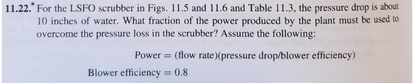
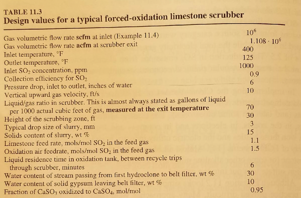
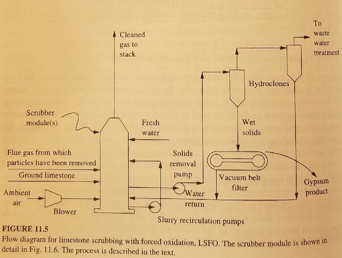
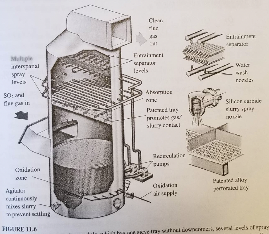
11.22.* For the LSFO scrubber in Figs. 11.5 and 11.6 and Table 11.3, the pressure drop is about 10 inches of water. What fraction of the power produced by the plant must be used to overcome the pressure loss in the scrubber? Assume the following: Power = (flow rate)(pressure drop/blower efficiency) Blower efficiency 0.8 TABLE 11.3 Design values for a typical forced-oxidation limestone scrubber 106 1.108. 106 400 125 1000 0.9 6 10 Gas volumetric flow rate scfm at inlet (Example 11.4) Gas volumetric flow rate acfm at scrubber exit Inlet temperature, F Outlet temperature, F Inlet SO2 concentration, ppm Collection efficiency for SO2 Pressure drop, inlet to outlet, inches of water Vertical upward gas velocity, ft/s Liquid/gas ratio in scrubber. This is almost always stated as gallons of liquid per 1000 actual cubic feet of gas, measured at the exit temperature Height of the scrubbing zone, ft Typical drop size of slurry, mm Solids content of slurry, wt % Limestone feed rate, mols/mol SO2 in the feed gas Oxidation air feedrate, mols/mol SO2 in the feed gas Liquid residence time in oxidation tank, between recycle trips through scrubber, minutes Water content of stream passing from first hydroclone to belt filter, wt % Water content of solid gypsum leaving belt filter, wt % Fraction of CaSO3 oxidized to CaSO4, mol/mol 70 30 3 15 1.1 1.5 6 30 10 0.95 waste A Cleaned gas to stack water treatment Hydroclones Scrubber module(s) Fresh Wet water solids Gypsum product Water Flue gas from which Solids particles have been removed removal Ground limestone pump Vacuum belt filter Ambient air Blower Slurry recirculation pumps FIGURE 11.5 Flow diagram for limestone scrubbing with forced oxidation, LSFO. The scrubber module is shown in detail in Fig. 11.6. The process is described in the text. return Clean flue gas out Entrainment separator Multiple interspatial spray levels Entrainment separator levels Water wash nozzles Absorption SO2 and zone flue gas in Patented tray Silicon carbide slurry spray nozzle promotes gas/ slurry contact Recirculation pumps Oxidation zone Oxidation air supply Patented alloy perforated tray Agitator continuously mixes slurry to prevent settling FIGURE 11.6 dule which has one sieve tray without downcomers, several levels of spray