Question
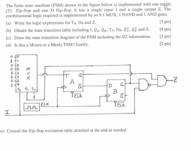
-The finite state machine (FSM) shown in the figure below is implemented with one toggle (T) flip-flop and one D flip-flop. It has a

-The finite state machine (FSM) shown in the figure below is implemented with one toggle (T) flip-flop and one D flip-flop. It has a single input I and a single output Z. The combinational logic required is implemented by an 8:1 MUX, I NAND and 1 AND gates. (a) Write the logic expressions for TA, DB and Z. (b) Obtain the state transition table including I, QA, QB, TA, DB, Q, Q and Z. (c) Draw the state transition diagram of the FSM including the I/Z information. (d) Is this a Moore or a Mealy FSM? Justify. [3 pts] [4 pts] [3 pts] [2 pts] 0 0-2 0-3 0-4 0-6 1-7 MOX 5 5, S H CLK Q A -Z D Q B PELR r CLR ote: Consult the flip-flop excitation table attached at the end as needed.
Step by Step Solution
There are 3 Steps involved in it
Step: 1

Get Instant Access to Expert-Tailored Solutions
See step-by-step solutions with expert insights and AI powered tools for academic success
Step: 2

Step: 3

Ace Your Homework with AI
Get the answers you need in no time with our AI-driven, step-by-step assistance
Get StartedRecommended Textbook for
Computer Organization and Design The Hardware Software Interface
Authors: David A. Patterson, John L. Hennessy
5th edition
124077269, 978-0124077263
Students also viewed these Programming questions
Question
Answered: 1 week ago
Question
Answered: 1 week ago
Question
Answered: 1 week ago
Question
Answered: 1 week ago
Question
Answered: 1 week ago
Question
Answered: 1 week ago
Question
Answered: 1 week ago
Question
Answered: 1 week ago
Question
Answered: 1 week ago
Question
Answered: 1 week ago
Question
Answered: 1 week ago
Question
Answered: 1 week ago
Question
Answered: 1 week ago
Question
Answered: 1 week ago
Question
Answered: 1 week ago
Question
Answered: 1 week ago
Question
Answered: 1 week ago
Question
Answered: 1 week ago
Question
Answered: 1 week ago
Question
Answered: 1 week ago
View Answer in SolutionInn App


