Question
The following sequential logic circuit is a latch. Its inputs are A & B, and its outputs are C and C'. C and C'

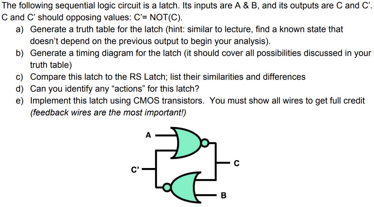
The following sequential logic circuit is a latch. Its inputs are A & B, and its outputs are C and C'. C and C' should opposing values: C'= NOT(C). a) Generate a truth table for the latch (hint: similar to lecture, find a known state that doesn't depend on the previous output to begin your analysis). b) Generate a timing diagram for the latch (it should cover all possibilities discussed in your truth table) c) Compare this latch to the RS Latch; list their similarities and differences d) Can you identify any "actions" for this latch? e) Implement this latch using CMOS transistors. You must show all wires to get full credit (feedback wires are the most important!) A D B
Step by Step Solution
3.56 Rating (153 Votes )
There are 3 Steps involved in it
Step: 1

Get Instant Access to Expert-Tailored Solutions
See step-by-step solutions with expert insights and AI powered tools for academic success
Step: 2

Step: 3

Ace Your Homework with AI
Get the answers you need in no time with our AI-driven, step-by-step assistance
Get StartedRecommended Textbook for
Cambridge International AS & A Level Computer Science
Authors: David Watson, Helen Williams
1st Edition
1510457593, 978-1510457591
Students also viewed these General Management questions
Question
Answered: 1 week ago
Question
Answered: 1 week ago
Question
Answered: 1 week ago
Question
Answered: 1 week ago
Question
Answered: 1 week ago
Question
Answered: 1 week ago
Question
Answered: 1 week ago
Question
Answered: 1 week ago
Question
Answered: 1 week ago
Question
Answered: 1 week ago
Question
Answered: 1 week ago
Question
Answered: 1 week ago
Question
Answered: 1 week ago
Question
Answered: 1 week ago
Question
Answered: 1 week ago
Question
Answered: 1 week ago
Question
Answered: 1 week ago
Question
Answered: 1 week ago
Question
Answered: 1 week ago
Question
Answered: 1 week ago
Question
Answered: 1 week ago
Question
Answered: 1 week ago
View Answer in SolutionInn App


