Answered step by step
Verified Expert Solution
Question
1 Approved Answer
The kinematic structure of a 3 DOF snow plowing robot is shown below at its home configuration. Coordinate frames are attached to the individual


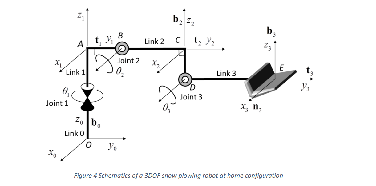
The kinematic structure of a 3 DOF snow plowing robot is shown below at its home configuration. Coordinate frames are attached to the individual links, as shown in the figure below. Joint 1 is a revolute joint about the zo axis. Joints 2 and 3 are also revolute joints about the horizontal axes at points B and D, respectively. Link 1 is an L-shaped rigid body connecting Joints 1 and 2. Coordinate frame A- xyz is attached to point A. Link 2 is also an L-shaped rigid body with a coordinate frame attached to point C. A large shovel is attached to the endpoint E. All joint angles are zero at the home configuration, and are measured in a right hand sense. Three unit vectors pointing in the directions of x,, y, and z, axes of the individual coordinate frames are indicated as n, t,b,, i = 0 ~ 3 . The link dimensions are OA = 10, AB = l, BC = l2, CD = 13,DE = 14. Answer the following questions. Z1 2 b Z2 b3 A t B Link 2 C t y Z3 Joint 2 x X E Link 1 02 Link 3 y3 0 Joint 3 03 X3 n3 Joint 1 Zo bo Link 0 Yo Figure 4 Schematics of a 3DOF snow plowing robot at home configuration
Step by Step Solution
There are 3 Steps involved in it
Step: 1

Get Instant Access to Expert-Tailored Solutions
See step-by-step solutions with expert insights and AI powered tools for academic success
Step: 2

Step: 3

Ace Your Homework with AI
Get the answers you need in no time with our AI-driven, step-by-step assistance
Get Started


