Question
The microwave has a door, a light, a power-tube, a cook button, a timer, a beeper and a display. When the oven is not in

The microwave has a door, a light, a power-tube, a cook button, a timer, a beeper and a display.
When the oven is not in use and the door is closed, the light and the power-tube are turned off and the display is blank.
When the door is open, the light stays on.
If the button is pushed when the door is closed and the oven is not operating, then the oven is activated for one minute. When the oven is activated, the light and the power-tube are turned on.
If the button is pushed when the oven is operating, one minute is added to the timer.
When the oven is operating, the display shows the number of seconds of cooking time remaining.
If the door is opened when the oven is operating, the power-tube is turned off.
When the cooking time is completed, the power-tube and light are turned off, and the beeper goes on (alarm sound) for 5 seconds.
Pushing the cook button when the door is open has no effect.
Cooking is only permitted when the door is closed and the button is pressed. Minimum cooking time is 1 minute per 1 press of the button.
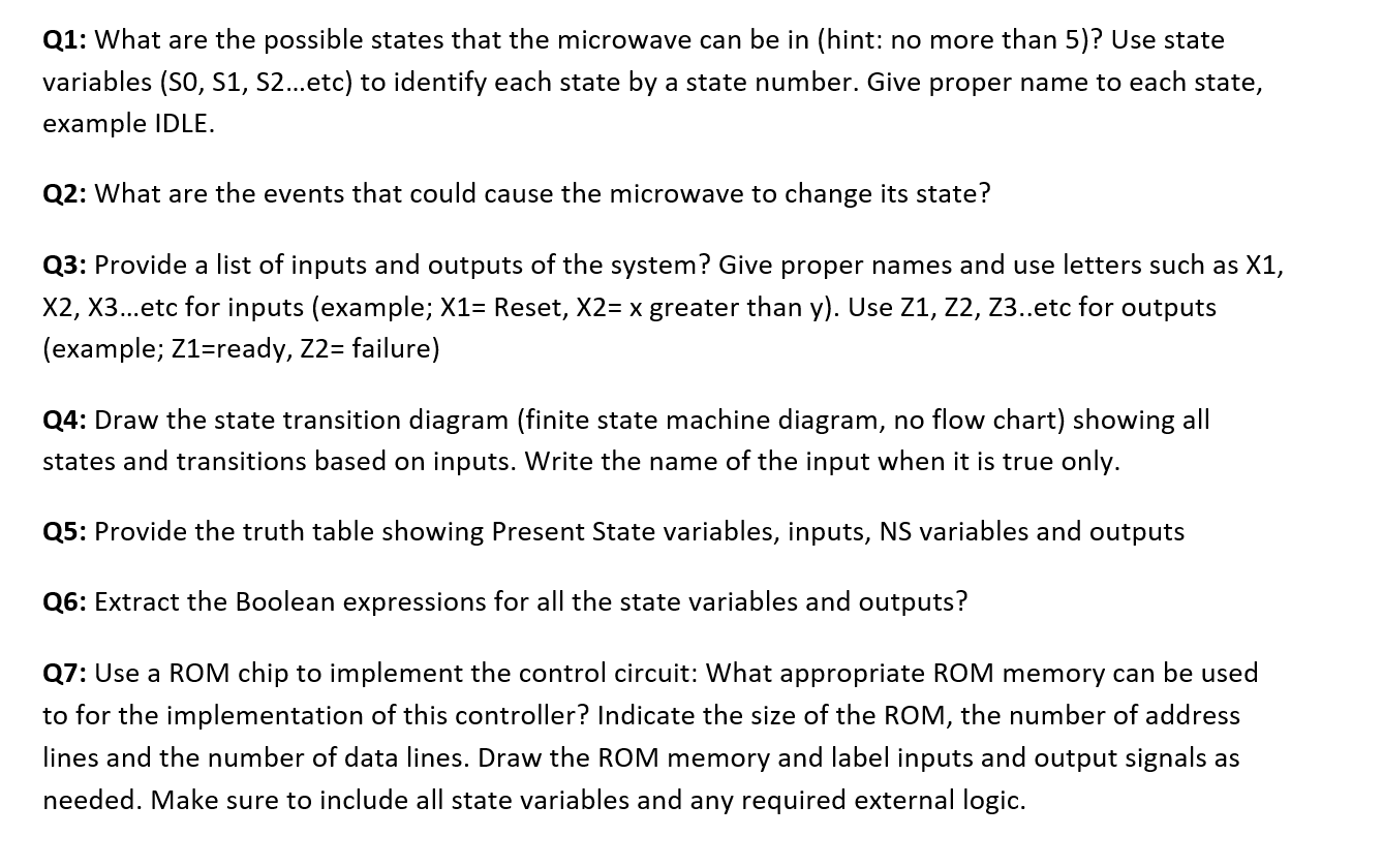
Q1: What are the possible states that the microwave can be in (hint: no more than 5)? Use state variables (S0, S1, S2etc) to identify each state by a state number. Give proper name to each state, example IDLE.
Q2: What are the events that could cause the microwave to change its state?
Q3: Provide a list of inputs and outputs of the system? Give proper names and use letters such as X1, X2, X3etc for inputs (example; X1= Reset, X2= x greater than y). Use Z1, Z2, Z3..etc for outputs (example; Z1=ready, Z2= failure)
Q4: Draw the state transition diagram (finite state machine diagram, no flow chart) showing all states and transitions based on inputs. Write the name of the input when it is true only.
Q5: Provide the truth table showing Present State variables, inputs, NS variables and outputs
Q6: Extract the Boolean expressions for all the state variables and outputs?
Q7: Use a ROM chip to implement the control circuit: What appropriate ROM memory can be used to for the implementation of this controller? Indicate the size of the ROM, the number of address lines and the number of data lines. Draw the ROM memory and label inputs and output signals as needed. Make sure to include all state variables and any required external logic.
Q1: What are the possible states that the microwave can be in (hint: no more than 5)? Use state variables (S0, S1, S2...etc) to identify each state by a state number. Give proper name to each state, example IDLE. Q2: What are the events that could cause the microwave to change its state? Q3: Provide a list of inputs and outputs of the system? Give proper names and use letters such as X1, X2, X3...etc for inputs (example; X1= Reset, X2= x greater than y). Use Z1, Z2, Z3..etc for outputs (example; Z1=ready, Z2= failure) Q4: Draw the state transition diagram (finite state machine diagram, no flow chart) showing all states and transitions based on inputs. Write the name of the input when it is true only. Q5: Provide the truth table showing Present State variables, inputs, NS variables and outputs Q6: Extract the Boolean expressions for all the state variables and outputs? Q7: Use a ROM chip to implement the control circuit: What appropriate ROM memory can be used to for the implementation of this controller? Indicate the size of the ROM, the number of address lines and the number of data lines. Draw the ROM memory and label inputs and output signals as needed. Make sure to include all state variables and any required external logic. Q1: What are the possible states that the microwave can be in (hint: no more than 5)? Use state variables (S0, S1, S2...etc) to identify each state by a state number. Give proper name to each state, example IDLE. Q2: What are the events that could cause the microwave to change its state? Q3: Provide a list of inputs and outputs of the system? Give proper names and use letters such as X1, X2, X3...etc for inputs (example; X1= Reset, X2= x greater than y). Use Z1, Z2, Z3..etc for outputs (example; Z1=ready, Z2= failure) Q4: Draw the state transition diagram (finite state machine diagram, no flow chart) showing all states and transitions based on inputs. Write the name of the input when it is true only. Q5: Provide the truth table showing Present State variables, inputs, NS variables and outputs Q6: Extract the Boolean expressions for all the state variables and outputs? Q7: Use a ROM chip to implement the control circuit: What appropriate ROM memory can be used to for the implementation of this controller? Indicate the size of the ROM, the number of address lines and the number of data lines. Draw the ROM memory and label inputs and output signals as needed. Make sure to include all state variables and any required external logicStep by Step Solution
There are 3 Steps involved in it
Step: 1

Get Instant Access to Expert-Tailored Solutions
See step-by-step solutions with expert insights and AI powered tools for academic success
Step: 2

Step: 3

Ace Your Homework with AI
Get the answers you need in no time with our AI-driven, step-by-step assistance
Get Started


