Answered step by step
Verified Expert Solution
Question
1 Approved Answer
The network depicted in the figure represents part of the EIU MAIN Network. The EIU MAIN network has been sub-divided in smaller networks for
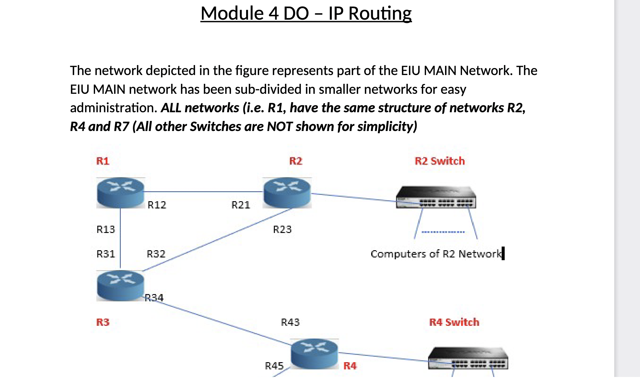
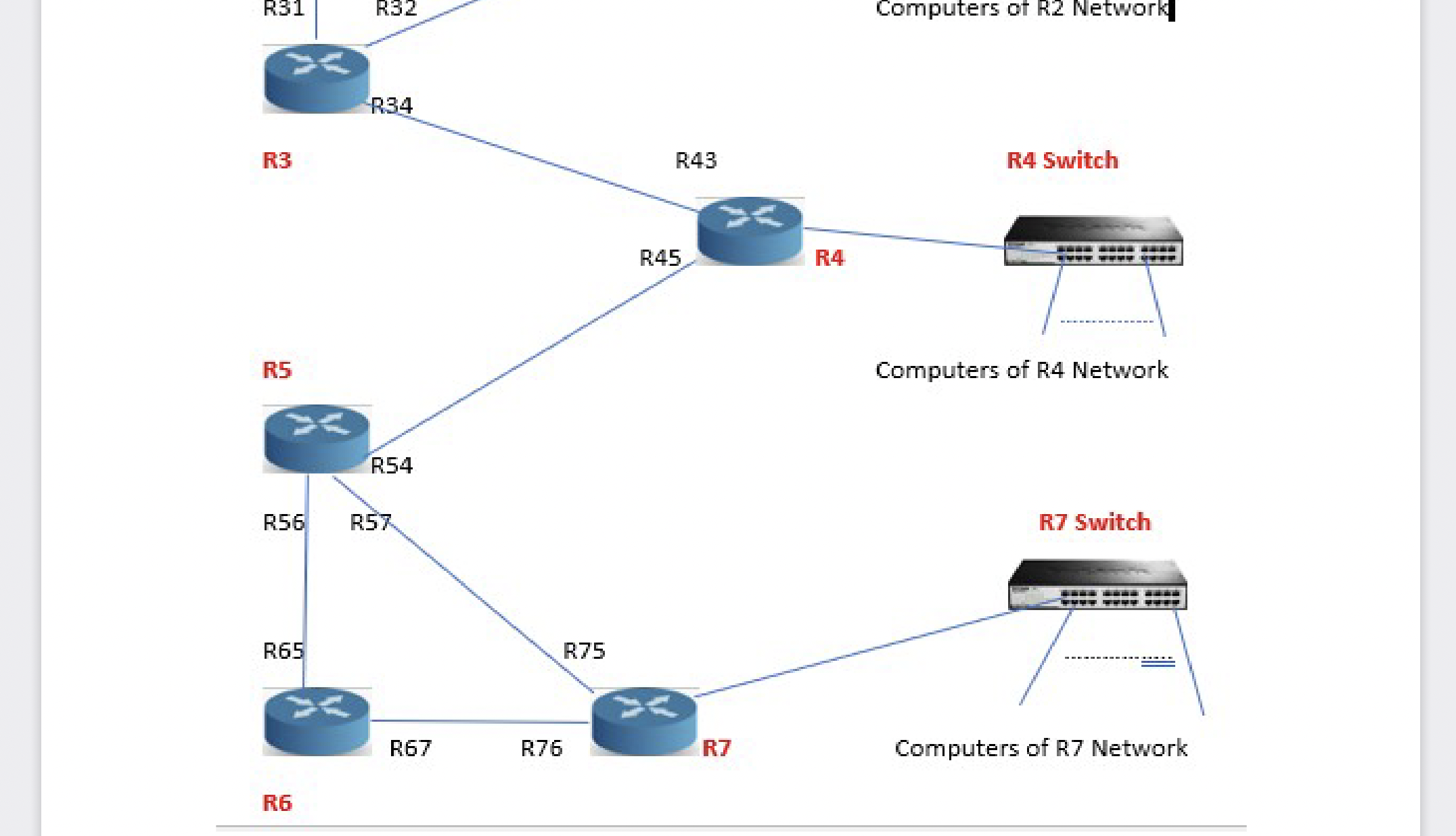
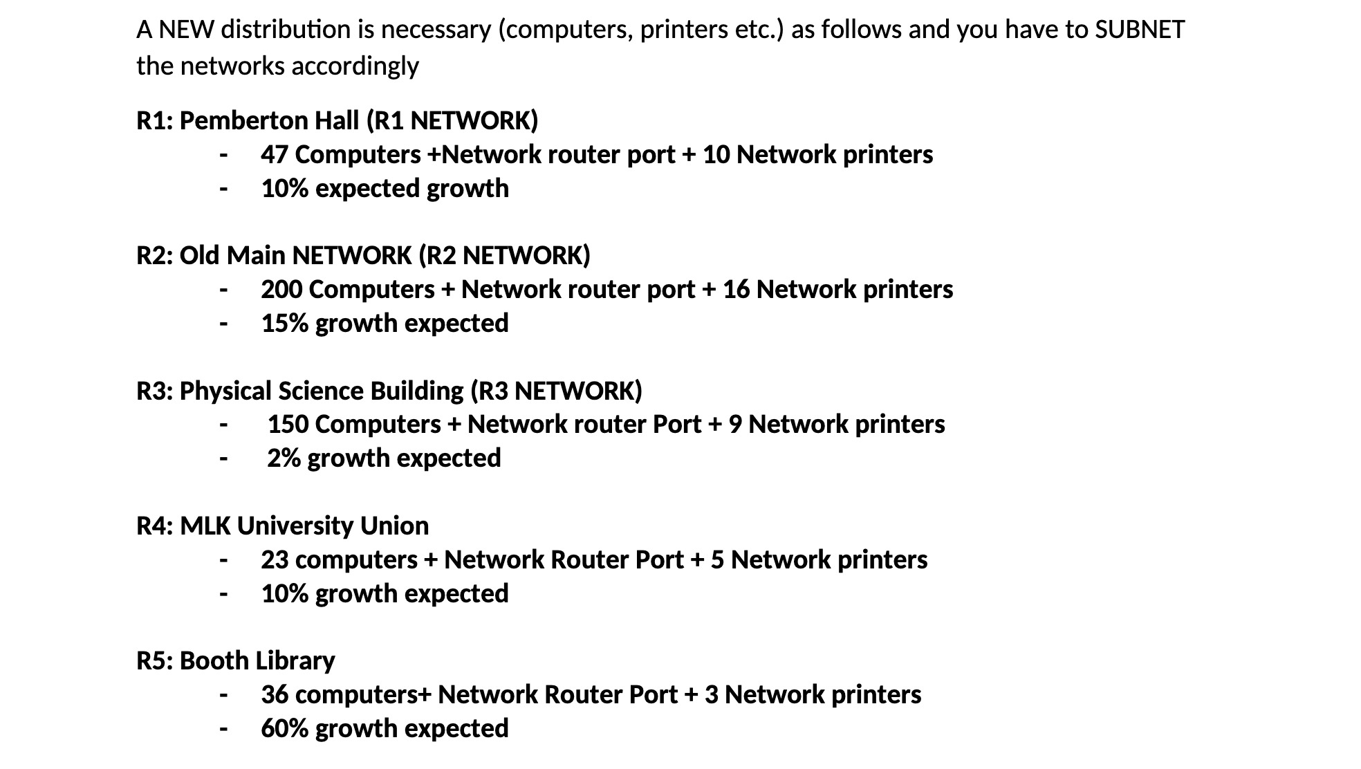
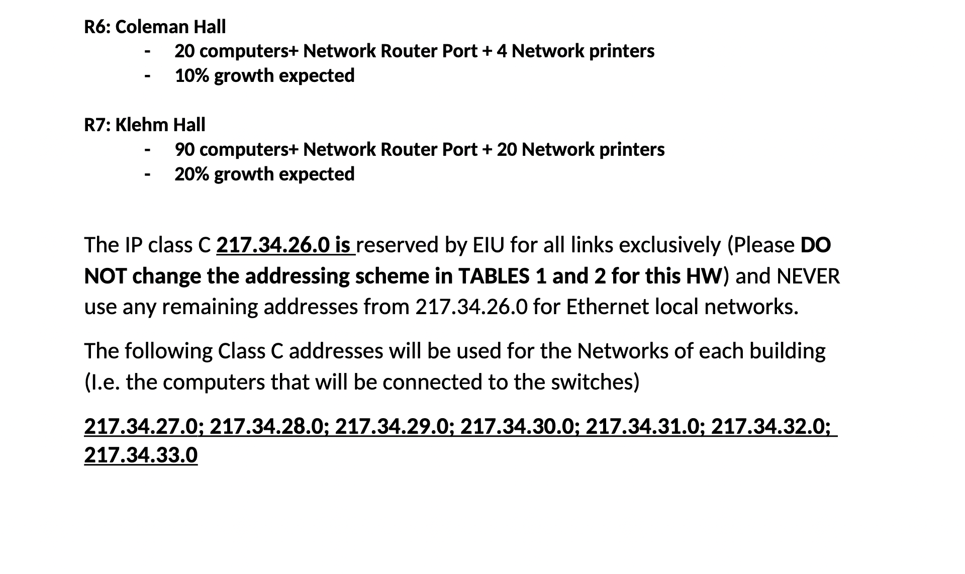

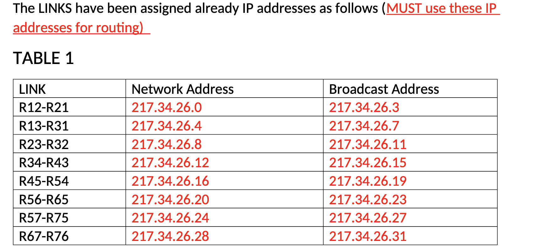
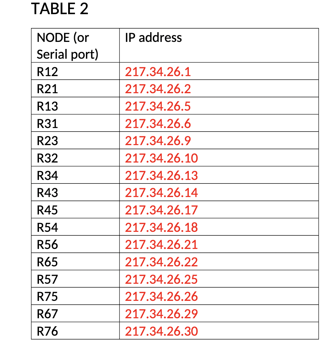
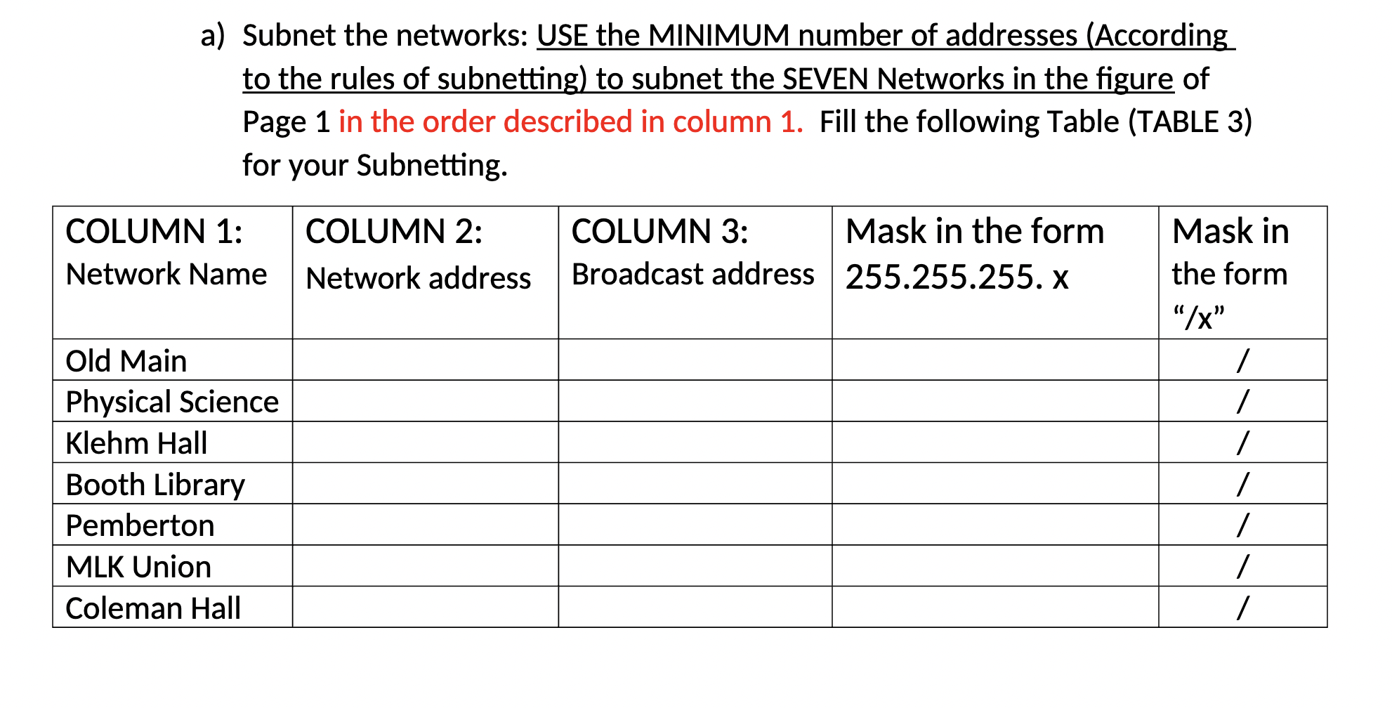
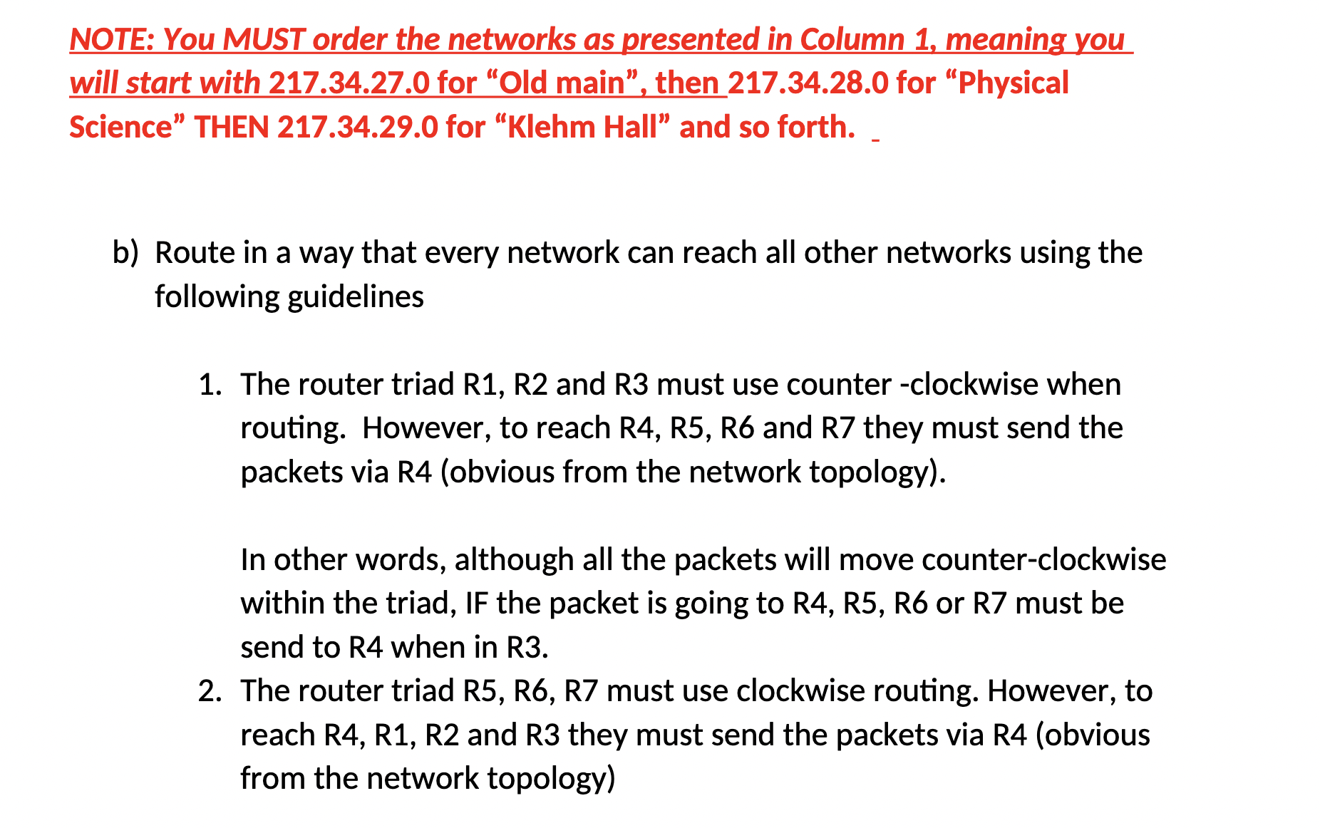
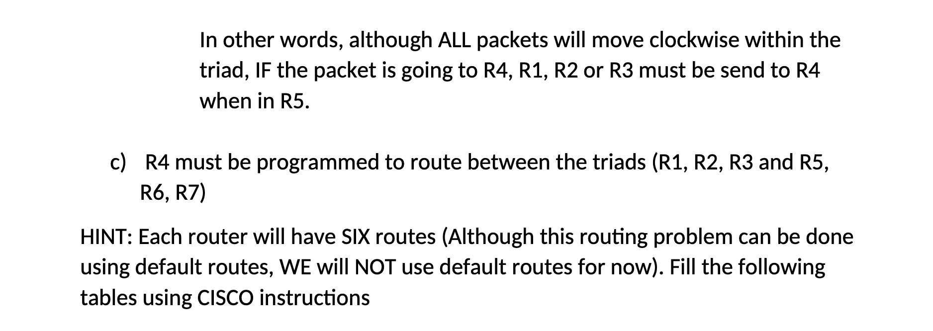
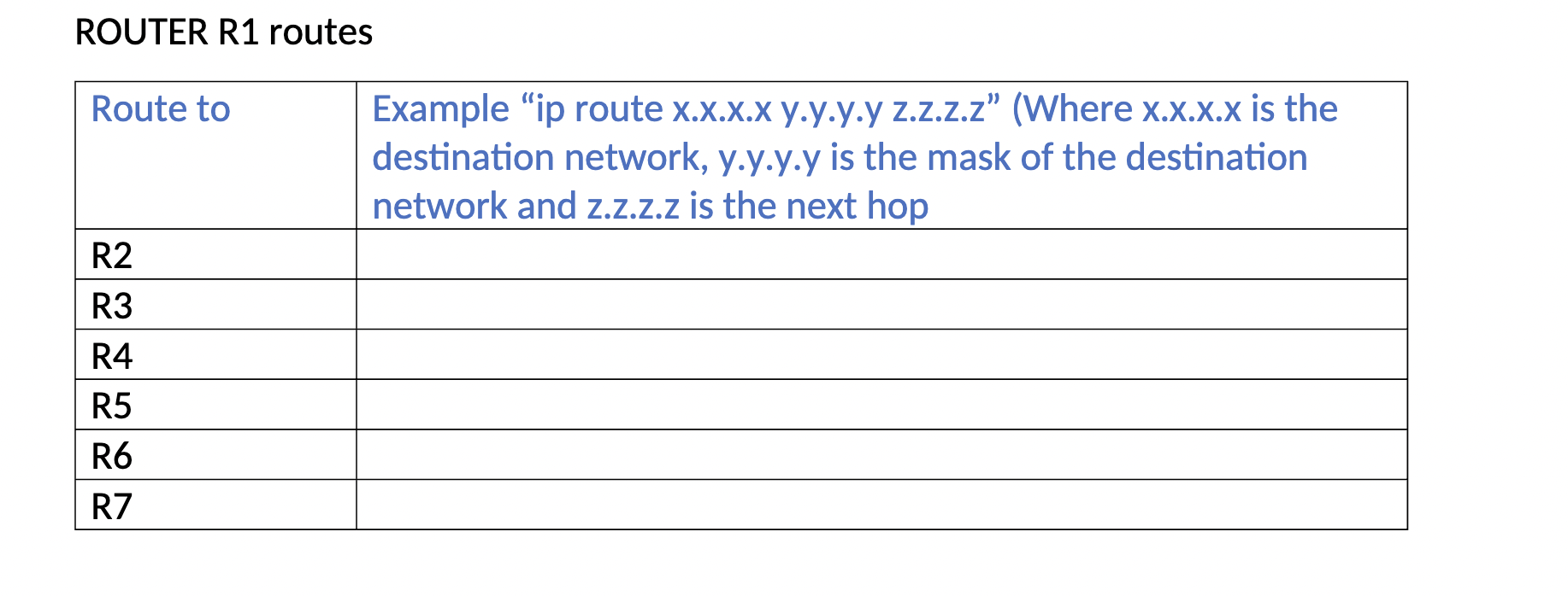
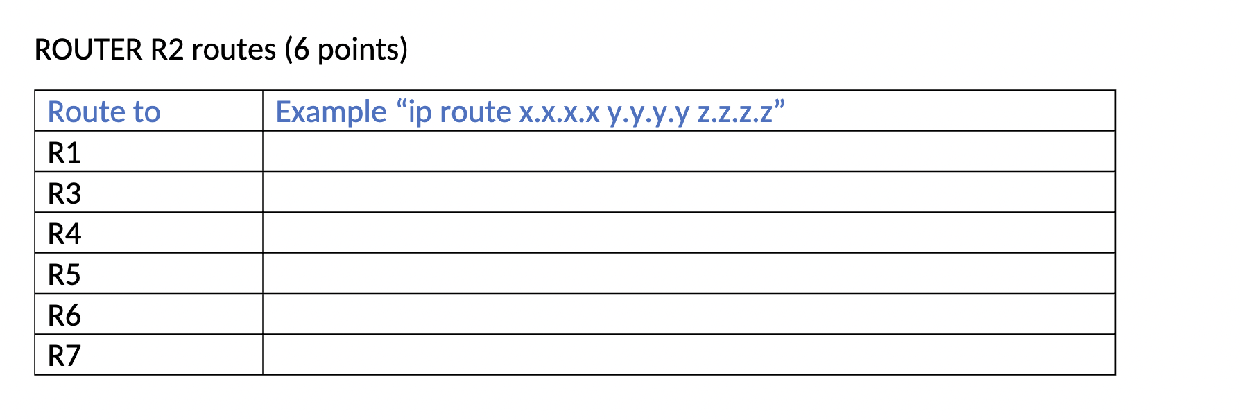
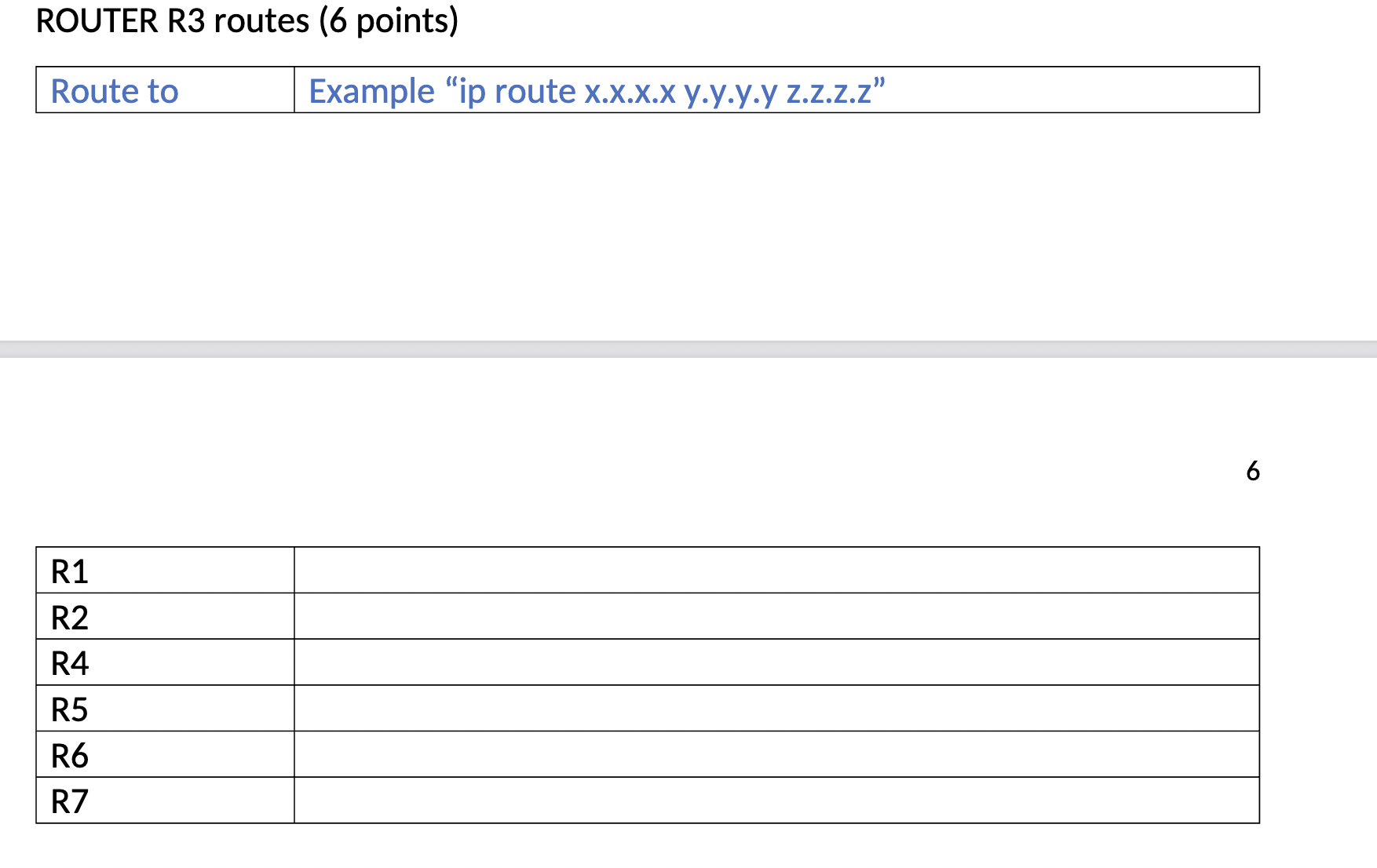
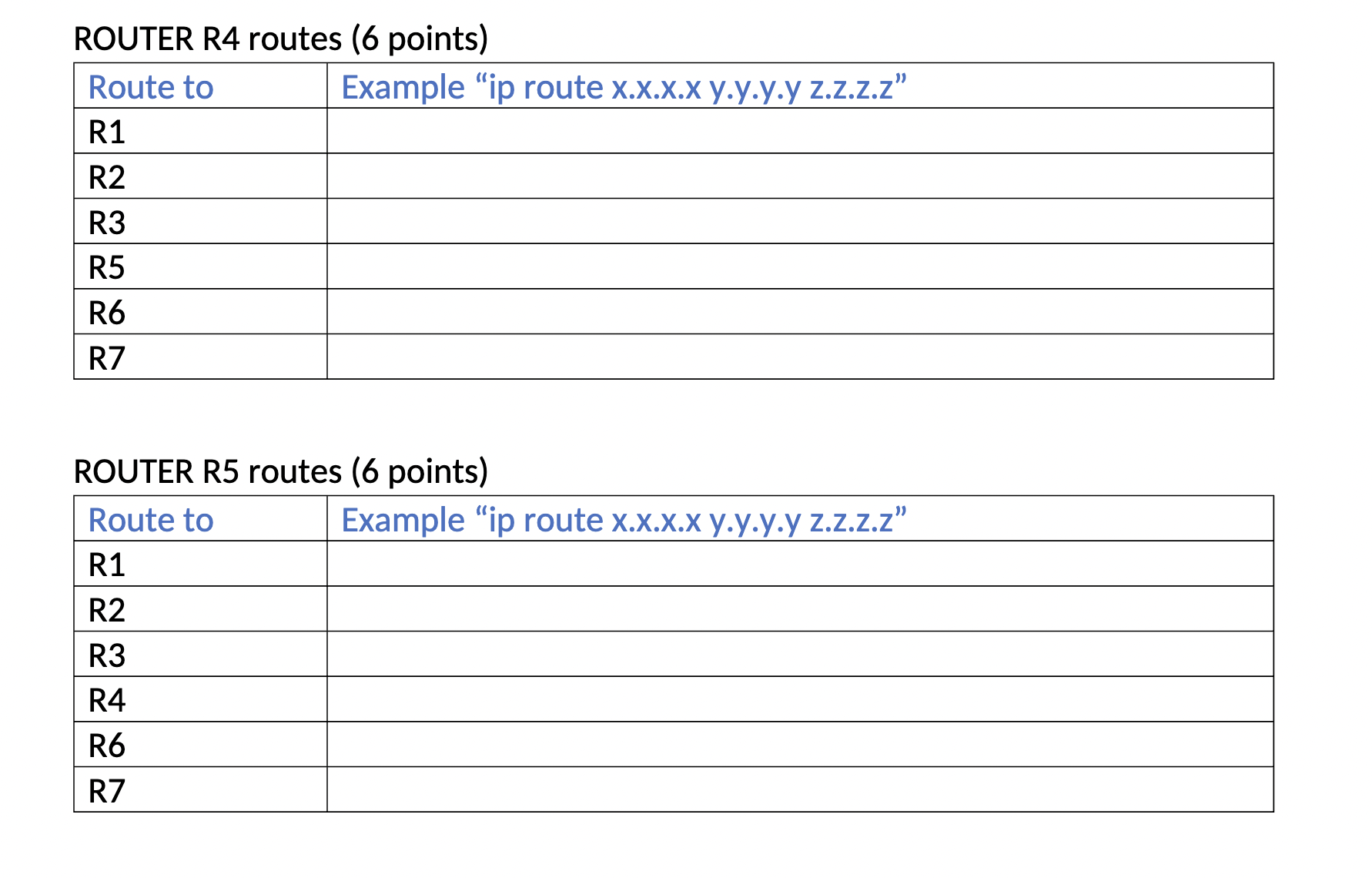

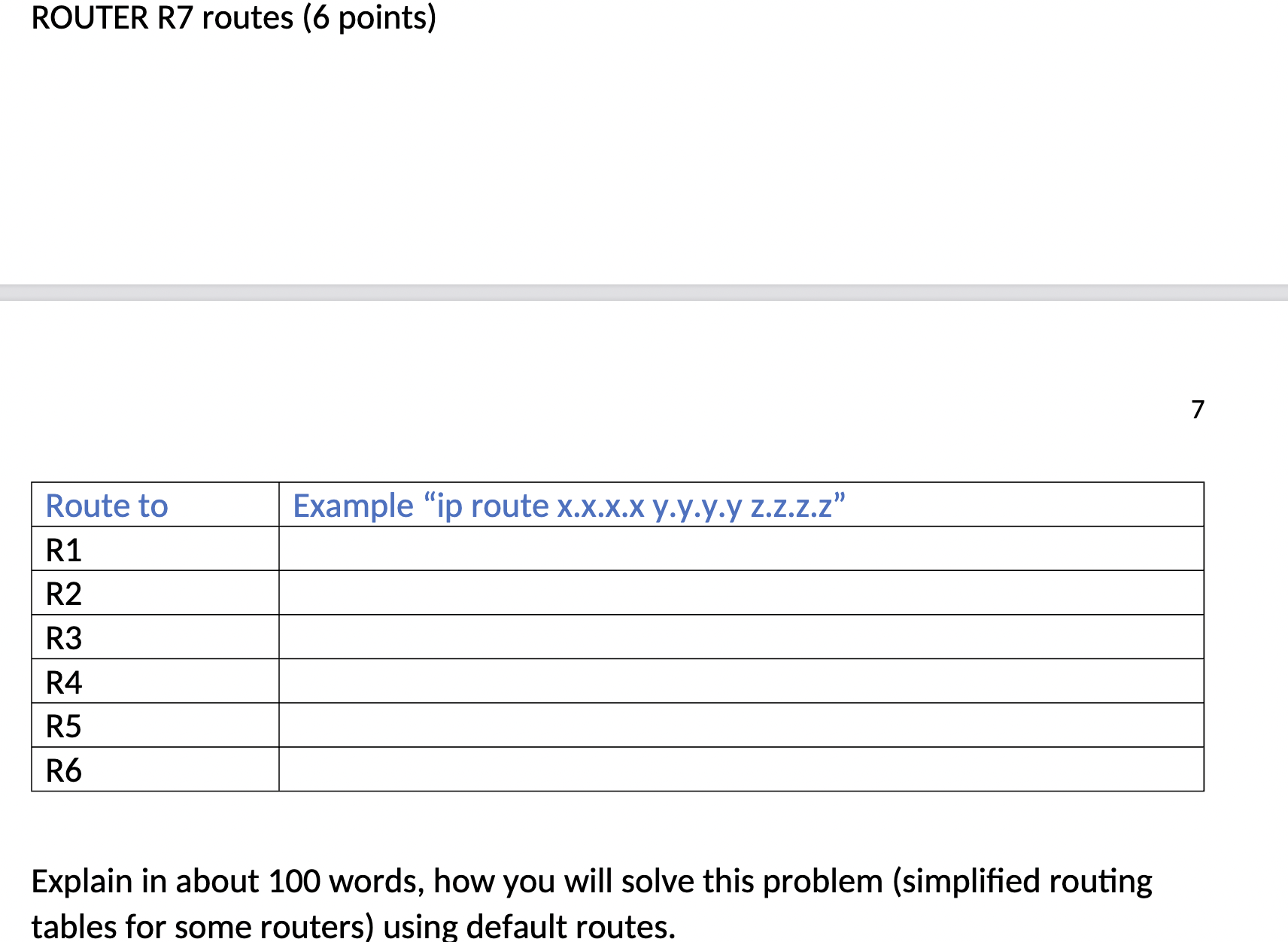
The network depicted in the figure represents part of the EIU MAIN Network. The EIU MAIN network has been sub-divided in smaller networks for easy administration. ALL networks (i.e. R1, have the same structure of networks R2, R4 and R7 (All other Switches are NOT shown for simplicity) R1 R13 R31 R3 R12 R32 Module 4 DO - IP Routing R34 R21 R2 R23 R43 R45 R4 R2 Switch Computers of R2 Network R4 Switch ---- - R31 R3 R5 R56 R65 R6 R32 R34 R54 R5X R67 R76 R75 R43 R45 R7 R4 Computers of R2 Network R4 Switch CA UN T **** **** *** Computers of R4 Network R7 Switch www Computers of R7 Network A NEW distribution is necessary (computers, printers etc.) as follows and you have to SUBNET the networks accordingly R1: Pemberton Hall (R1 NETWORK) 47 Computers +Network router port + 10 Network printers 10% expected growth R2: Old Main NETWORK (R2 NETWORK) 200 Computers + Network router port + 16 Network printers 15% growth expected R3: Physical Science Building (R3 NETWORK) - 150 Computers + Network router Port + 9 Network printers 2% growth expected R4: MLK University Union 23 computers + Network Router Port + 5 Network printers 10% growth expected R5: Booth Library 36 computers+ Network Router Port + 3 Network printers 60% growth expected R6: Coleman Hall 20 computers+ Network Router Port + 4 Network printers 10% growth expected R7: Klehm Hall - 90 computers+ Network Router Port + 20 Network printers 20% growth expected The IP class C 217.34.26.0 is reserved by EIU for all links exclusively (Please DO NOT change the addressing scheme in TABLES 1 and 2 for this HW) and NEVER use any remaining addresses from 217.34.26.0 for Ethernet local networks. The following Class C addresses will be used for the Networks of each building (I.e. the computers that will be connected to the switches) 217.34.27.0; 217.34.28.0; 217.34.29.0; 217.34.30.0; 217.34.31.0; 217.34.32.0; 217.34.33.0 The LINKS have been assigned already IP addresses as follows (MUST use these IP addresses for routing) TABLE 1 LINK R12-R21 R13-R31 R23-R32 R34-R43 R45-R54 R56-R65 R57-R75 R67-R76 Network Address 217.34.26.0 217.34.26.4 217.34.26.8 217.34.26.12 217.34.26.16 217.34.26.20 217.34.26.24 217.34.26.28 Broadcast Address 217.34.26.3 217.34.26.7 217.34.26.11 217.34.26.15 217.34.26.19 217.34.26.23 217.34.26.27 217.34.26.31 TABLE 2 NODE (or Serial port) R12 R21 R13 R31 R23 R32 R34 R43 R45 R54 R56 R65 R57 R75 R67 R76 IP address 217.34.26.1 217.34.26.2 217.34.26.5 217.34.26.6 217.34.26.9 217.34.26.10 217.34.26.13 217.34.26.14 217.34.26.17 217.34.26.18 217.34.26.21 217.34.26.22 217.34.26.25 217.34.26.26 217.34.26.29 217.34.26.30 a) Subnet the networks: USE the MINIMUM number of addresses (According to the rules of subnetting) to subnet the SEVEN Networks in the figure of Page 1 in the order described in column 1. Fill the following Table (TABLE 3) for your Subnetting. COLUMN 1: Network Name Old Main Physical Science Klehm Hall Booth Library Pemberton MLK Union Coleman Hall COLUMN 2: Network address COLUMN 3: Broadcast address Mask in the form 255.255.255.x Mask in the form "/x" / 1 1 / 1 1 / NOTE: You MUST order the networks as presented in Column 1, meaning you will start with 217.34.27.0 for "Old main", then 217.34.28.0 for "Physical Science" THEN 217.34.29.0 for "Klehm Hall" and so forth. b) Route in a way that every network can reach all other networks using the following guidelines 1. The router triad R1, R2 and R3 must use counter -clockwise when routing. However, to reach R4, R5, R6 and R7 they must send the packets via R4 (obvious from the network topology). In other words, although all the packets will move counter-clockwise within the triad, IF the packet is going to R4, R5, R6 or R7 must be send to R4 when in R3. 2. The router triad R5, R6, R7 must use clockwise routing. However, to reach R4, R1, R2 and R3 they must send the packets via R4 (obvious from the network topology) In other words, although ALL packets will move clockwise within the triad, IF the packet is going to R4, R1, R2 or R3 must be send to R4 when in R5. c) R4 must be programmed to route between the triads (R1, R2, R3 and R5, R6, R7) HINT: Each router will have SIX routes (Although this routing problem can be done using default routes, WE will NOT use default routes for now). Fill the following tables using CISCO instructions ROUTER R1 routes Route to R2 R3 R4 R5 R6 R7 Example "ip route x.x.x.x y.y.y.y z.z.z.z" (Where x.x.x.x is the destination network, y.y.y.y is the mask of the destination network and z.z.z.z is the next hop ROUTER R2 routes (6 points) Route to R1 R3 R4 R5 R6 R7 Example "ip route x.x.x.x y.y.y.yz.z.z.z" ROUTER R3 routes (6 points) Route to R1 R2 R4 R5 R6 R7 Example "ip route x.x.x.x y.y.y.y z.z.z.z" 6 ROUTER R4 routes (6 points) Route to R1 R2 R3 R5 R6 R7 Example "ip route x.x.x.x y.yy.y z.z.z.z" ROUTER R5 routes (6 points) Route to R1 R2 R3 R4 R6 R7 Example "ip route x.x.x.x y.yy.y z.z.z.z" ROUTER R6 routes (6 points) Route to R1 R2 R3 R4 R5 R7 Example "ip route x.x.x.x y.yy.y z.z.z.z" ROUTER R7 routes (6 points) Route to R1 R2 R3 R4 R5 R6 Example "ip route x.x.x.x y.y.y.y z.z.z.z" Explain in about 100 words, how you will solve this problem (simplified routing tables for some routers) using default routes. 7
Step by Step Solution
There are 3 Steps involved in it
Step: 1

Get Instant Access to Expert-Tailored Solutions
See step-by-step solutions with expert insights and AI powered tools for academic success
Step: 2

Step: 3

Ace Your Homework with AI
Get the answers you need in no time with our AI-driven, step-by-step assistance
Get Started


