

Question: The pull-up network of a complex gate is shown in Fig.4.14. Determine the Booleanfunction implemented by the gate, and complete the electrical schematic by
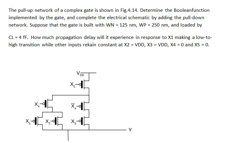
The pull-up network of a complex gate is shown in Fig.4.14. Determine the Booleanfunction implemented by the gate, and complete the electrical schematic by adding the pull-down network. Suppose that the gate is built with WN = 125 nm, WP = 250 nm, and loaded by CL = 4 fF. How much propagation delay will it experience in response to X1 making a low-to- high transition while other inputs rekain constant at X2 = VDD, X3 = VDD, X4 = 0 and X5 = 0. X X- X- DD - Y
Step by Step Solution
3.34 Rating (154 Votes )
There are 3 Steps involved in it
Given problem has been solved wi... View full answer

Get step-by-step solutions from verified subject matter experts