

Answered step by step
Verified Expert Solution
Question
1 Approved Answer
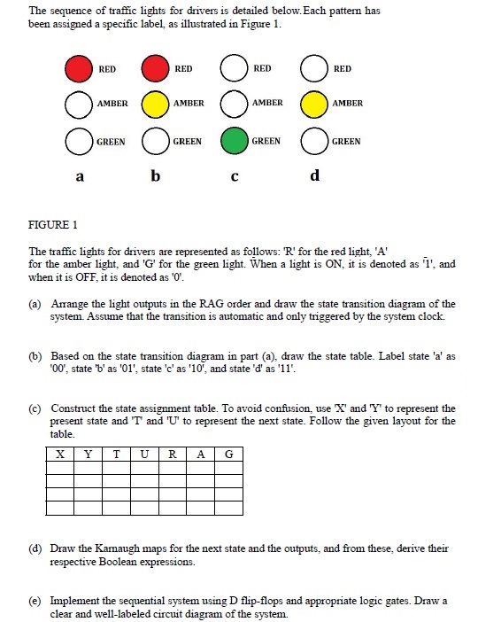
The sequence of traffic lights for drivers is detailed below. Each pattern has been assigned a specific label, as illustrated in Figure 1 . The
The sequence of traffic lights for drivers is detailed below. Each pattern has been assigned a specific label, as illustrated in Figure
The traffic lights for drivers are represented as follows: R for the red light, A for the amber light, and for the green light. When a light is ON it is denoted as and when it is OFF, it is denoted as
a Arrange the light outputs in the RAG order and draw the state transition diagram of the system. Assume that the transition is automatic and only triggered by the system clock.
b Based on the state transition diagram in part a draw the state table. Label state a as state b as state c as and state d as
c Construct the state assignment table. To avoid confusion, use and to represent the
present state and and to represent the next state. Follow the given layout for the table.
d Draw the Karnaugh maps for the next state and the outputs, and from these, derive their respective Boolean expressions.
e Implement the sequential system using D flipflops and appropriate logic gates. Draw a clear and welllabeled circuit diagram of the system.
Step by Step Solution
There are 3 Steps involved in it
Step: 1

Get Instant Access to Expert-Tailored Solutions
See step-by-step solutions with expert insights and AI powered tools for academic success
Step: 2

Step: 3
Ace Your Homework with AI
Get the answers you need in no time with our AI-driven, step-by-step assistance
Get Started
Oracle Database 19c DBA By Examples Installation And Administration
Authors: Ravinder Gupta
1st Edition
B09FC7TQJ6, 979-8469226970