Question
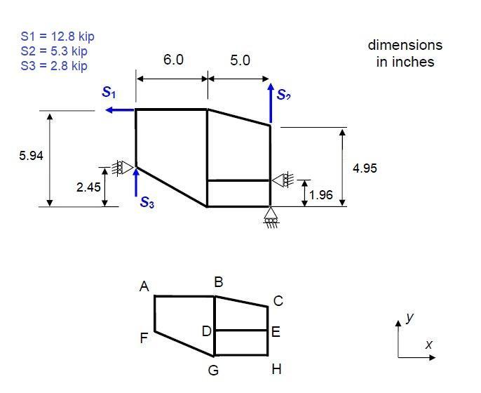
The tapered stiffened beam below is loaded by forces as shown. The beam is assumed to consist of stiffeners carrying only direct stress and shear
The tapered stiffened beam below is loaded by forces as shown. The beam is assumed to consist of stiffeners carrying only direct stress and shear panels carrying only shear stress. The material used has E = 10500 ksi, G = 3900 ksi, (sigma)ty = 48 ksi,(sigma)cy = 38 ksi, (sigma)sy = 37 ksi.

(a) Calculate the stiffener axial loads (lbf) at the end of each beam segment and the shear flows (lbf/in) along each panel edge.
For stiffeners, size to yield stress (in tension or compression), considering the maximum load in each segment (i.e. each segment can have a different area). For the shear panels, size to yield stress (in shear, maximum in each panel) or shear buckling, whichever is critical. For the buckling calculation, assume that the shear panels are simply supported on all edges, and for the tapered panels use the smaller edge dimensions (i.e. assume a rectangular panel with the smaller of the width and height edge dimensions). When sizing, use a minimum possible area of 0.30 in2 and a minimum possible thickness of 0.0052 in.
Stiffener axial loads (lbf): Use positive for tension and negative for compression
Segment (Seg) and location (Loc), e.g. AB A is the force in stiffener segment AB at location A
| Seg | Loc | |
| AB | A | |
| B | ||
| BC | B | |
| C | ||
| AF | A | |
| F | ||
| BD | B | |
| D | ||
| CE | C | |
| E | ||
| DE | D | |
| E | ||
| DG | D | |
| G | ||
| EH | E | |
| H | ||
| FG | F | |
| G | ||
| GH | G | |
| H |
Shear flows (lbf/in). Only absolute values, signs ignored
Panel and edge, e.g. ABGF AB is panel ABGF, edge AB
| ABGF | AB | |
| BG | ||
| GF | ||
| FA | ||
| BCED | BC | |
| CE | ||
| ED | ||
| DB | ||
| DEHG | DE | |
| EH | ||
| HG | ||
| GD |
S1 = 12.8 kip S2 = 5.3 kip S3 = 2.8 kip 5.94 2.45 S # S3 A F 6.0 B G 5.0 S K C E H 1.96 dimensions in inches 4.95 y X
Step by Step Solution
3.72 Rating (176 Votes )
There are 3 Steps involved in it
Step: 1

Get Instant Access to Expert-Tailored Solutions
See step-by-step solutions with expert insights and AI powered tools for academic success
Step: 2

Step: 3

Ace Your Homework with AI
Get the answers you need in no time with our AI-driven, step-by-step assistance
Get Started


