Answered step by step
Verified Expert Solution
Link Copied!

Question

1 Approved Answer

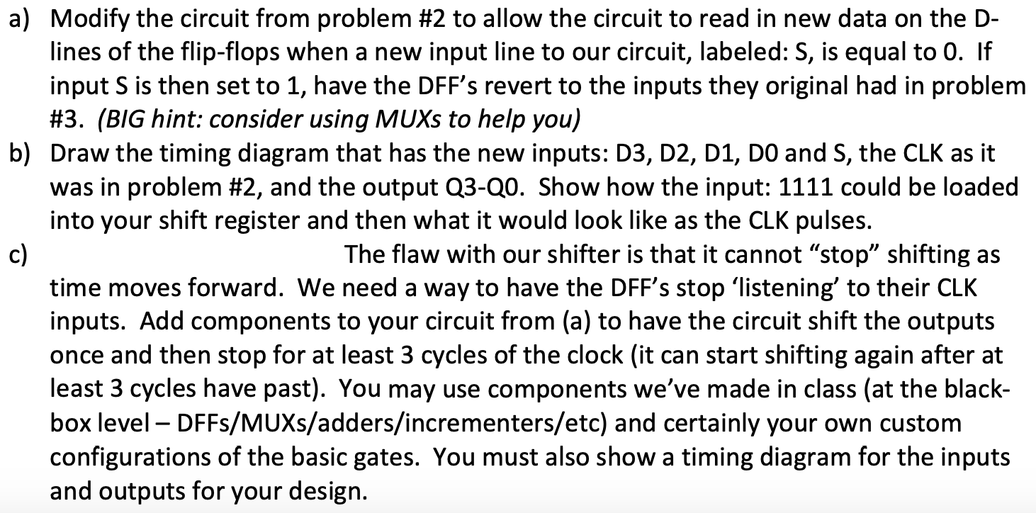
This is the circuit that needs to be modified: Q3 Q2 Q1 QO D Q D Q Q DQ GND (OV) CLK a) Modify the

This is the circuit that needs to be modified:image text in transcribedimage text in transcribed

Q3 Q2 Q1 QO D Q D Q Q DQ GND (OV) CLK a) Modify the circuit from problem #2 to allow the circuit to read in new data on the D- lines of the flip-flops when a new input line to our circuit, labeled: S, is equal to 0. If input S is then set to 1, have the DFF's revert to the inputs they original had in problem #3. (BIG hint: consider using MUXs to help you) b) Draw the timing diagram that has the new inputs: D3, D2, D1, DO and S, the CLK as it was in problem #2, and the output Q3-20. Show how the input: 1111 could be loaded into your shift register and then what it would look like as the CLK pulses. c) The flaw with our shifter is that it cannot stop shifting as time moves forward. We need a way to have the DFF's stop listening to their CLK inputs. Add components to your circuit from (a) to have the circuit shift the outputs once and then stop for at least 3 cycles of the clock (it can start shifting again after at least 3 cycles have past). You may use components we've made in class (at the black- box level - DFFs/MUXs/adders/incrementers/etc) and certainly your own custom configurations of the basic gates. You must also show a timing diagram for the inputs and outputs for your design. Q3 Q2 Q1 QO D Q D Q Q DQ GND (OV) CLK a) Modify the circuit from problem #2 to allow the circuit to read in new data on the D- lines of the flip-flops when a new input line to our circuit, labeled: S, is equal to 0. If input S is then set to 1, have the DFF's revert to the inputs they original had in problem #3. (BIG hint: consider using MUXs to help you) b) Draw the timing diagram that has the new inputs: D3, D2, D1, DO and S, the CLK as it was in problem #2, and the output Q3-20. Show how the input: 1111 could be loaded into your shift register and then what it would look like as the CLK pulses. c) The flaw with our shifter is that it cannot stop shifting as time moves forward. We need a way to have the DFF's stop listening to their CLK inputs. Add components to your circuit from (a) to have the circuit shift the outputs once and then stop for at least 3 cycles of the clock (it can start shifting again after at least 3 cycles have past). You may use components we've made in class (at the black- box level - DFFs/MUXs/adders/incrementers/etc) and certainly your own custom configurations of the basic gates. You must also show a timing diagram for the inputs and outputs for your design

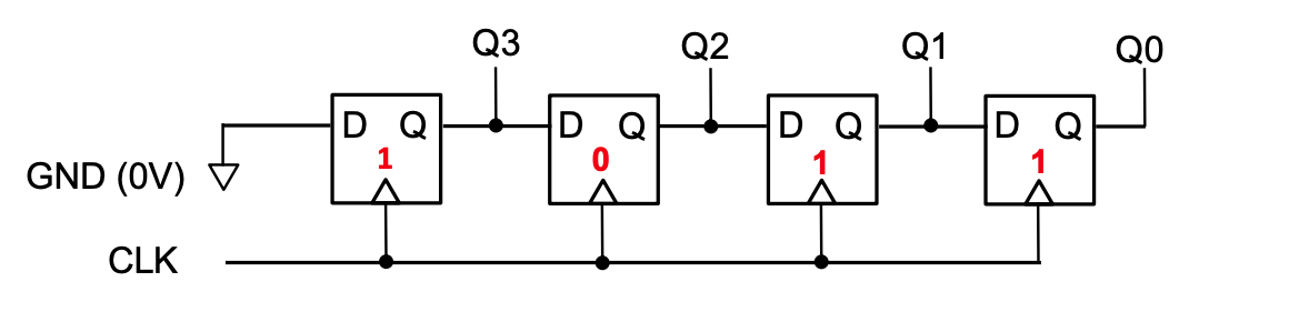
Step by Step Solution

There are 3 Steps involved in it

Step: 1

blur-text-image

Get Instant Access to Expert-Tailored Solutions

See step-by-step solutions with expert insights and AI powered tools for academic success

Step: 2

blur-text-image

Step: 3

blur-text-image

Ace Your Homework with AI

Get the answers you need in no time with our AI-driven, step-by-step assistance

Get Started

Recommended Textbook for

More Books

Students also viewed these Databases questions