Question
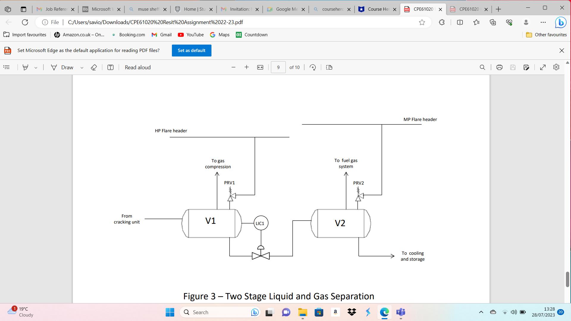
Two-stage separation process (30 Marks) Figure 3 describes a two-stage separation process. A mixture of liquid hydrocarbon product and gas from a cracking unit enters
Two-stage separation process (30 Marks) Figure 3 describes a two-stage separation process. A mixture of liquid hydrocarbon product and gas from a cracking unit enters a high-pressure separator V1. The vessel operates at a pressure of 50 barg (design pressure 55 barg) and a temperature of 30C. The gas offtake (methane) is directed to a compression system for subsequent treatment and export into the sales gas pipeline. The liquid from V1 (mostly butane) is transferred to the low-pressure separator V2. V2 operates at a pressure of 10 barg (design pressure 12 barg) also at a temperature of 30C. Gas from this vessel (a mixture of methane, ethane and propane) is directed to the fuel gas system. Pressure relief valves are located on each vessel. Vessel V1 relief discharges via PRV1 to a HP (high pressure) 10" flare line (back pressure 2 barg) and vessel V2 relief via PRV2 to a 18" MP (medium pressure) flare line (back pressure 0.7 barg). The flow from V1 to V2 is under level control (via loop LIC1) which maintains vessel V1 at 50% full. The orifice diameter for the level control valve when fully open is equivalent to a diameter of 30mm.
Question 3a [10 Marks] Based on the following information determine the required sizing of PRV1 and PRV2 based on fire engulfment (you may assume single gas phase relief). Vessels V1 and V2 - length = 7m, diameter = 2.5m, hemispherical ends. For this part of the exercise, you may assume that any rise in pressure is due to vaporisation of n-butane liquid and the gas discharging from the relief vent will be pure n-butane (see Figure 4 for vapour pressure data).
Question 3b [10 Marks] Quantify the change to the relief valve sizes if the vessels are fitted with fireproof insulation.
Question 3c [10 Marks] For PRV2 determine the sizing for gas breakthrough due to loss of liquid level in V1 as a result of LIC1 valve failing open (again you may assume single gas phase relief).

M Job Referer X Bb Microsoft V X muse sheff X Home | Stu X MInvitation: X Google Me X coursehero X Course Her X CPE61020 X PDF CPE61020 + File | C:/Users/savio/Downloads/CPE61020%20Resit%20Assignment%2022-23.pdf {3 {" Import favourites hp Amazon.co.uk - On... Booking.com M Gmail YouTube G Maps Countdown Set Microsoft Edge as the default application for reading PDF files? Set as default Draw T Read aloud HP Flare header To gas compression PRV1 9 of 10 To fuel gas system PRV2 From cracking unit V1 LIC1 V2 MP Flare header Figure 3 - Two Stage Liquid and Gas Separation a 19C Q Search Cloudy To cooling and storage 33 60 6 X Other favourites C < 13:28 28/07/2023
Step by Step Solution
There are 3 Steps involved in it
Step: 1

Get Instant Access to Expert-Tailored Solutions
See step-by-step solutions with expert insights and AI powered tools for academic success
Step: 2

Step: 3

Ace Your Homework with AI
Get the answers you need in no time with our AI-driven, step-by-step assistance
Get Started


