 undefined
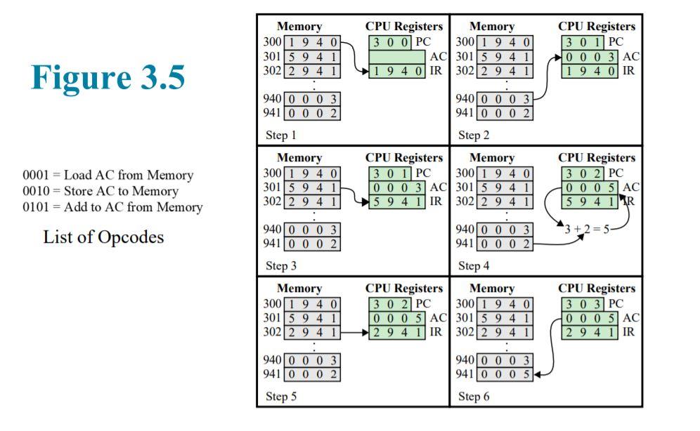
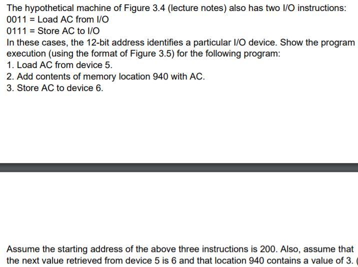
Memory 300 1 9 4 OH 301 5 94 3022 9 4 1 CPU Registers Memory 30 OPC 300 1 9 4 0 AC 301 5 9 4 1 9 4 0 IR 3022 9 4 1 CPU Registers 3 0 1PC 000 3 AC 1 9 4 0 IR Figure 3.5 940 0 0 0 3 941 0 0 0 940 0 0 0 3 941 0 0 0 2 Step 1 Memory 300 1 9 4 0 301 5 9 4 1 3022 9 4 1 . 940 0 0 0 3 941 0 0 0 2 0001 = Load AC from Memory 0010 = Store AC to Memory 0101 = Add to AC from Memory List of Opcodes Step 2 CPU Registers Memory 30 1PC 300 1 940 0 0 0 3 AC 301 5 9 4 5 9 4 1 IR 3022 9 4 CPU Registers 3 0 2 PC 0 0 0 5 AC 5 9 4 1 R 3 + 2 = 5 940 0 0 0 941 0 0 0 Step 3 Memory 300/1 9 4 0 301 5 9 4 1 3022 94 1 Step 4 CPU Registers Memory 3 0 2 PC 300 1 9 4 0 0 0 0 5 AC 301 5 9 4 2 9 4 1 IR 302 2 9 4 1 CPU Registers 3 0 3 PC O O O 5 AC 2 9 4 1 IR 940 0 0 0 941 0 0 0 2 940 0 0 0 941 0 0 0 Step 5 Step 6 The hypothetical machine of Figure 3.4 (lecture notes) also has two I/O instructions: 0011 = Load AC from I/O 0111 = Store AC to I/O In these cases, the 12-bit address identifies a particular I/O device. Show the program execution (using the format of Figure 3.5) for the following program: 1. Load AC from device 5. 2. Add contents of memory location 940 with AC. 3. Store AC to device 6. Assume the starting address of the above three instructions is 200. Also, assume that the next value retrieved from device 5 is 6 and that location 940 contains a value of 3. Memory 300 1 9 4 OH 301 5 94 3022 9 4 1 CPU Registers Memory 30 OPC 300 1 9 4 0 AC 301 5 9 4 1 9 4 0 IR 3022 9 4 1 CPU Registers 3 0 1PC 000 3 AC 1 9 4 0 IR Figure 3.5 940 0 0 0 3 941 0 0 0 940 0 0 0 3 941 0 0 0 2 Step 1 Memory 300 1 9 4 0 301 5 9 4 1 3022 9 4 1 . 940 0 0 0 3 941 0 0 0 2 0001 = Load AC from Memory 0010 = Store AC to Memory 0101 = Add to AC from Memory List of Opcodes Step 2 CPU Registers Memory 30 1PC 300 1 940 0 0 0 3 AC 301 5 9 4 5 9 4 1 IR 3022 9 4 CPU Registers 3 0 2 PC 0 0 0 5 AC 5 9 4 1 R 3 + 2 = 5 940 0 0 0 941 0 0 0 Step 3 Memory 300/1 9 4 0 301 5 9 4 1 3022 94 1 Step 4 CPU Registers Memory 3 0 2 PC 300 1 9 4 0 0 0 0 5 AC 301 5 9 4 2 9 4 1 IR 302 2 9 4 1 CPU Registers 3 0 3 PC O O O 5 AC 2 9 4 1 IR 940 0 0 0 941 0 0 0 2 940 0 0 0 941 0 0 0 Step 5 Step 6 The hypothetical machine of Figure 3.4 (lecture notes) also has two I/O instructions: 0011 = Load AC from I/O 0111 = Store AC to I/O In these cases, the 12-bit address identifies a particular I/O device. Show the program execution (using the format of Figure 3.5) for the following program: 1. Load AC from device 5. 2. Add contents of memory location 940 with AC. 3. Store AC to device 6. Assume the starting address of the above three instructions is 200. Also, assume that the next value retrieved from device 5 is 6 and that location 940 contains a value of 3